【STM32 开发】| INA219采集电压、电流值
目录
- 前言
- 1 原理图
- 2 IIC地址说明
- 3 寄存器地址说明
- 4 开始工作前配置
- 5 程序代码
- 1)驱动程序
- 2)头文件
- 3) 测试代码
前言
INA219 是一款具备 I2C 或 SMBUS 兼容接口的分流器和功率监测计。该器件监测分流器电压降和总线电源电压,转换次数和滤波选项可通过编程设定。可编程校准值与内部乘法器相结合,支持直接读取电流值(单位:安培)。通过附加乘法寄存器可计算功率(单位:瓦)。I2C 或 SMBUS 兼容接口 具有 16 个可编程地址。
INA219 可在 0V 至 26V 范围内感测总线中的分压。该器件由 3V 至 5.5V 单电源供电,电源的最大流耗为1mA。INA219 的工作温度范围为 -40°C 至 125°C。
1 原理图

2 IIC地址说明

此测试时A0、A1都下拉接地,所以INA219的IIC通信地址为1000000B
3 寄存器地址说明

- 0x00 配置寄存器,用来配置工作模式、采集范围以及其他参数
- 0x01 分流电阻两端的电压
- 0x02 总线电压(IN-到GND的电压差)
- 0x03 功率
- 0x04 经过分流电阻两端的电流
- 0x05 校准寄存器,用于对测量结果进行校准
4 开始工作前配置
- 0x00 寄存器Bit 13:设置检测最大检测电压 0 = 16V,1 = 32V (此处项目需要测3V到5V的电压,故设置Bit 13 为 0)
- 0x00 寄存器Bit 11-12:设置总线分流电阻最大的电压(此处项目需要测0A到5A的电流,故设置Bit 11-12 为 01,即量程±80mV,可测电流±8A)
- 0x00 寄存器Bit 0-2:设置工作模式(默认)
- 0x05 寄存器:设置基准值(根据需要测的电压、电流范围再套入公式得出结果)
由以下公式可得出0x05的配置值。
C a l = t r u n c ( 0.04096 C u r r e n t L S B × R s h u n t ) Cal = trunc\left ( \frac{0.04096}{CurrentLSB\times Rshunt} \right ) Cal=trunc(CurrentLSB×Rshunt0.04096)
C u r r e n t L S B = M a x i m u m E x p e c t e d C u r r e n t 2 15 CurrentLSB = \frac{Maximum Expected Current}{2^{15}} CurrentLSB=215MaximumExpectedCurrent
数据手册说明文档

5 程序代码
1)驱动程序
#include "main.h"
#include "ina219aidcnr_helper.h"uint16_t ina219_calibrationValue;
uint16_t ina219_currentDivider_mA;
float ina219_powerMultiplier_mW;/*** @brief  The IIC reads 16bit data from the specified register address.* @param  ina219 Slave configuration structure of the IIC.* @param  registerAddress Internal memory address.* @return 16 bit register data.*/
uint16_t INA219_ReadDataForRegister_16Bits(INA219_t *ina219, uint8_t registerAddress)
{uint8_t Value[2];HAL_I2C_Mem_Read(ina219->ina219_i2c, (INA219_ADDRESS<<1), registerAddress, 1, Value, 2, 1000);return ((Value[0] << 8) | Value[1]);
}/*** @brief  Writes 16 bits of data to the register.* @param  ina219 Slave configuration structure of the IIC.* @param  registerAddress Internal memory address.* @param  Value 16 bits of data to be written.*/
void INA219_WriteDataToRegister_16Bits(INA219_t *ina219, uint8_t registerAddress, uint16_t Value)
{uint8_t regAddr[2];/* High Byte */regAddr[0] = (Value >> 8) & 0xff;/* Low Byte */regAddr[1] = (Value >> 0) & 0xff;HAL_I2C_Mem_Write(ina219->ina219_i2c, (INA219_ADDRESS<<1), registerAddress, 1, (uint8_t*)regAddr, 2, 1000);
}/*** @brief  Read bus voltage.* @param  ina219 Slave configuration structure of the IIC.* @return Read voltage value, unit mV.*/
uint16_t INA219_ReadBusVoltage(INA219_t *ina219)
{uint16_t result = INA219_ReadDataForRegister_16Bits(ina219, INA219_REG_BUS_VOLTAGE);/* return mV */return ((result >> 3  ) * 4);
}/*** @brief  Read current register value.* @param  ina219 Slave configuration structure of the IIC.* @return Current register value.*/
uint16_t INA219_ReadCurrentRaw(INA219_t *ina219)
{uint16_t result = INA219_ReadDataForRegister_16Bits(ina219, INA219_REG_CURRENT);return (result);
}/*** @brief  Read current register value, unit mA.* @param  ina219 Slave configuration structure of the IIC.* @return Current value.*/
uint16_t INA219_ReadCurrent_mA(INA219_t *ina219)
{uint16_t result = INA219_ReadCurrentRaw(ina219);return (result / ina219_currentDivider_mA);
}/*** @brief  Read current register value, unit mV.* @param  ina219 Slave configuration structure of the IIC.* @return Shunt Voltage value.*/
uint16_t INA219_ReadShuntVoltage_mV(INA219_t *ina219)
{uint16_t result = INA219_ReadDataForRegister_16Bits(ina219, INA219_REG_SHUNT_VOLTAGE);/* When multiple sign bits are present, they will all be the same value.* Negative numbers are represented in 2's complement format.* Generate the 2's complement of a negative number by complementing the absolute value binary number and adding 1.* Extend the sign, denoting a negative number by setting the MSB = 1.* Extend the sign to any additional sign bits to form the 16-bit word. */if(result > MAX_SHUNT_RANGE){result = 65536 - MAX_SHUNT_RANGE;}/* Shunt voltage, unit mV. */return (result / 100);
}/*** @brief  INA219 system reset.* @param  ina219 Slave configuration structure of the IIC.*/
void INA219_Reset(INA219_t *ina219)
{INA219_WriteDataToRegister_16Bits(ina219, INA219_REG_CONFIG, INA219_CONFIG_RESET);HAL_Delay(1);
}/*** @brief Set calibration register.* @param ina219 Slave configuration structure of the IIC.* @param calibrationData Calibrated data.*/
void INA219_SetCalibration(INA219_t *ina219, uint16_t calibrationData)
{INA219_WriteDataToRegister_16Bits(ina219, INA219_REG_CALIBRATION, calibrationData);
}/*** @brief  Gets the value of the configuration register.* @param  ina219 Slave configuration structure of the IIC.* @return Configuration Register value.*/
uint16_t INA219_GetConfigInfo(INA219_t *ina219)
{uint16_t result = INA219_ReadDataForRegister_16Bits(ina219, INA219_REG_CONFIG);return result;
}/*** @brief Set configuration register.* @param ina219 Slave configuration structure of the IIC.* @param configData Configuration data.*/
void INA219_SetConfig(INA219_t *ina219, uint16_t configData)
{INA219_WriteDataToRegister_16Bits(ina219, INA219_REG_CONFIG, configData);
}/*** @brief The measurement results are calibrated. Voltage range is 16V, Current range is 8A.* @param ina219 Slave configuration structure of the IIC.*/
void INA219_SetCalibration_16V_8A(INA219_t *ina219)
{uint16_t configInfo = INA219_CONFIG_VOLTAGE_RANGE_16V |INA219_CONFIG_GAIN_2_80MV | INA219_CONFIG_BADCRES_12BIT |INA219_CONFIG_SADCRES_12BIT_1S_532US |INA219_CONFIG_MODE_SANDBVOLT_CONTINUOUS;// Current_LSB = Maximum Expected Current / 2^15 = (80 / 10) / 2^15 = 0.0002// Cal = 0.04096 / (Current_LSB / R) = 0.04096 / (0.0002A * 0.01R) = 20480 = 0x5000// Calibration Register = 20480ina219_calibrationValue = 20480;// 1mA = Current_LSB * bits = 200uA * 5bit (5 bit/mA)ina219_currentDivider_mA = 5;// 1mW = Power_LSB * bits = 4mW * 0.25bit (0.25f bit/mW)ina219_powerMultiplier_mW = 0.25f;INA219_SetCalibration(ina219, ina219_calibrationValue);INA219_SetConfig(ina219, configInfo);
}/*** @brief  Ina219 driver initialization* @param  ina219 Slave configuration structure of the IIC.* @param  i2c Pointer to a I2C_HandleTypeDef structure that contains*             the configuration information for the specified I2C.* @param  Address  Configuration data.* @return status.*/
uint8_t INA219_Init(INA219_t *ina219, I2C_HandleTypeDef *i2c, uint8_t Address)
{ina219->ina219_i2c = i2c;ina219->Address = Address;ina219_currentDivider_mA = 0;ina219_powerMultiplier_mW = 0;uint8_t ina219_isReady = HAL_I2C_IsDeviceReady(i2c, (Address << 1), 3, 2);if(ina219_isReady == HAL_OK){INA219_Reset(ina219);INA219_SetCalibration_16V_8A(ina219);return 1;}else{return 0;}
}
2)头文件
#ifndef INA219AIDCNR_HELPER_H
#define INA219AIDCNR_HELPER_H#define INA219_ADDRESS 							        (0x40)
#define MAX_SHUNT_RANGE                     			(0x0FA0)/* Register */
#define	INA219_REG_CONFIG						        (0x00)
#define	INA219_REG_SHUNT_VOLTAGE				    	(0x01)
#define	INA219_REG_BUS_VOLTAGE					    	(0x02)
#define	INA219_REG_POWER						        (0x03)
#define	INA219_REG_CURRENT						      	(0x04)
#define	INA219_REG_CALIBRATION					    	(0x05)
//
#define INA219_CONFIG_RESET 					      	(0x8000)
//
#define INA219_CONFIG_VOLTAGE_RANGE_16V					(0x0000)      // 0-16V Range
#define INA219_CONFIG_VOLTAGE_RANGE_32V					(0x2000)      // 0-32V Range#define	INA219_CONFIG_GAIN_1_40MV				    	(0x0000)      // Gain 1, 40mV Range
#define	INA219_CONFIG_GAIN_2_80MV				    	(0x0800)      // Gain 2, 80mV Range
#define	NA219_CONFIG_GAIN_4_160MV				    	(0x1000)      // Gain 4, 160mV Range
#define	INA219_CONFIG_GAIN_8_320MV				  		(0x1800)      // Gain 8, 320mV Range#define	INA219_CONFIG_BADCRES_9BIT				      	(0x0000)  // 9-bit bus res = 0..511
#define	INA219_CONFIG_BADCRES_10BIT				      	(0x0080)  // 10-bit bus res = 0..1023
#define	INA219_CONFIG_BADCRES_11BIT				      	(0x0100)  // 11-bit bus res = 0..2047
#define	INA219_CONFIG_BADCRES_12BIT				      	(0x0180)  // 12-bit bus res = 0..4097
#define	INA219_CONFIG_BADCRES_12BIT_2S_1060US 			(0x0480)  // 2 x 12-bit bus samples averaged together
#define	INA219_CONFIG_BADCRES_12BIT_4S_2130US	  		(0x0500)  // 4 x 12-bit bus samples averaged together
#define	INA219_CONFIG_BADCRES_12BIT_8S_4260US	  		(0x0580)  // 8 x 12-bit bus samples averaged together
#define	INA219_CONFIG_BADCRES_12BIT_16S_8510US			(0x0600)  // 16 x 12-bit bus samples averaged together
#define	INA219_CONFIG_BADCRES_12BIT_32S_17MS	  		(0x0680)  // 32 x 12-bit bus samples averaged together
#define	INA219_CONFIG_BADCRES_12BIT_64S_34MS	  		(0x0700)  // 64 x 12-bit bus samples averaged together
#define	INA219_CONFIG_BADCRES_12BIT_128S_69MS	  		(0x0780)  // 128 x 12-bit bus samples averaged together#define	INA219_CONFIG_SADCRES_9BIT_1S_84US		  		(0x0000)  // 1 x 9-bit shunt sample
#define	INA219_CONFIG_SADCRES_10BIT_1S_148US	  		(0x0008)  // 1 x 10-bit shunt sample
#define	INA219_CONFIG_SADCRES_11BIT_1S_276US	  		(0x0010)  // 1 x 11-bit shunt sample
#define	INA219_CONFIG_SADCRES_12BIT_1S_532US	  		(0x0018)  // 1 x 12-bit shunt sample
#define	INA219_CONFIG_SADCRES_12BIT_2S_1060US	  		(0x0048)  // 2 x 12-bit shunt samples averaged together
#define	INA219_CONFIG_SADCRES_12BIT_4S_2130US	  		(0x0050)  // 4 x 12-bit shunt samples averaged together
#define	INA219_CONFIG_SADCRES_12BIT_8S_4260US	 	 	(0x0058)  // 8 x 12-bit shunt samples averaged together
#define	INA219_CONFIG_SADCRES_12BIT_16S_8510US			(0x0060)  // 16 x 12-bit shunt samples averaged together
#define	INA219_CONFIG_SADCRES_12BIT_32S_17MS	  		(0x0068)  // 32 x 12-bit shunt samples averaged together
#define	INA219_CONFIG_SADCRES_12BIT_64S_34MS	  		(0x0070)  // 64 x 12-bit shunt samples averaged together
#define	INA219_CONFIG_SADCRES_12BIT_128S_69MS	  		(0x0078)  // 128 x 12-bit shunt samples averaged together#define INA219_CONFIG_MODE_MASK					        0x07
#define	INA219_CONFIG_MODE_POWERDOWN			       	0x00
#define	INA219_CONFIG_MODE_SVOLT_TRIGGERED		   		0x01
#define	INA219_CONFIG_MODE_BVOLT_TRIGGERED		   		0x02
#define	INA219_CONFIG_MODE_SANDBVOLT_TRIGGERED	 		0x03
#define	INA219_CONFIG_MODE_ADCOFF				        0x04
#define	INA219_CONFIG_MODE_SVOLT_CONTINUOUS		   		0x05
#define	INA219_CONFIG_MODE_BVOLT_CONTINUOUS		   		0x06
#define	INA219_CONFIG_MODE_SANDBVOLT_CONTINUOUS  		0x07typedef struct
{I2C_HandleTypeDef 	*ina219_i2c;uint8_t				Address;
} INA219_t;uint8_t INA219_Init(INA219_t *ina219, I2C_HandleTypeDef *i2c, uint8_t Address);
uint16_t INA219_ReadBusVoltage(INA219_t *ina219);
uint16_t INA219_ReadCurrent_mA(INA219_t *ina219);
uint16_t INA219_ReadCurrent_raw(INA219_t *ina219);
uint16_t INA219_ReadShuntVoltage_mV(INA219_t *ina219);
uint16_t INA219_ReadDataForRegister_16Bits(INA219_t *ina219, uint8_t registerAddress);
uint16_t INA219_GetConfigInfo(INA219_t *ina219);void INA219_Reset(INA219_t *ina219);
void INA219_SetCalibration(INA219_t *ina219, uint16_t calibrationData);
void INA219_SetConfig(INA219_t *ina219, uint16_t configData);
void INA219_SetCalibration_16V_8A(INA219_t *ina219);
void INA219_WriteDataToRegister_16Bits(INA219_t *ina219, uint8_t registerAddress, uint16_t Value);#endif //INA219AIDCNR_HELPER_H
3) 测试代码
int main(void)
{/* USER CODE BEGIN 1 */uint16_t vbus, vshunt, current;/* USER CODE END 1 *//* MCU Configuration--------------------------------------------------------*//* Reset of all peripherals, Initializes the Flash interface and the Systick. */HAL_Init();/* USER CODE BEGIN Init *//* USER CODE END Init *//* Configure the system clock */SystemClock_Config();/* USER CODE BEGIN SysInit *//* USER CODE END SysInit *//* Initialize all configured peripherals */MX_GPIO_Init();MX_USART1_UART_Init();MX_I2C2_Init();/* USER CODE BEGIN 2 */while(!INA219_Init(&ina219, &hi2c2, INA219_ADDRESS)){}/* USER CODE END 2 *//* Infinite loop *//* USER CODE BEGIN WHILE */while (1){/* USER CODE END WHILE *//* USER CODE BEGIN 3 */vbus = INA219_ReadBusVoltage(&ina219);vshunt = INA219_ReadShuntVoltage_mV(&ina219);current = INA219_ReadCurrent_mA(&ina219);sprintf(strBuffer, "INA219 param: vbus:%d mV; current:%d mA\r\n", vbus, current);HAL_UART_Transmit(&huart1, strBuffer, strlen(strDataBuf), 0xff);UserDelay_ms(500);}
相关文章:
【STM32 开发】| INA219采集电压、电流值
目录 前言1 原理图2 IIC地址说明3 寄存器地址说明4 开始工作前配置5 程序代码1)驱动程序2)头文件3) 测试代码 前言 INA219 是一款具备 I2C 或 SMBUS 兼容接口的分流器和功率监测计。该器件监测分流器电压降和总线电源电压,转换次数和滤波选项…...
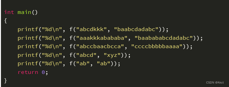
蓝桥杯每日一题203.11.7
题目描述 题目分析 使用dp思维,当前位置是否可行是有上一位置推来,计算出最大的可行位置即可 #include <stdio.h> #include <string.h>#define N 256 int f(const char* s1, const char* s2) {int a[N][N];int len1 strlen(s1);int len2 …...
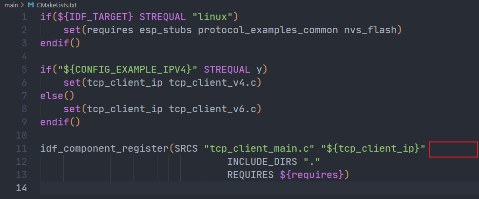
ESP32建立TCP连接
ESP32建立TCP连接 1.搭建ESP-IDF开发环境 搭建开发环境直接从官网下载即可。 https://docs.espressif.com/projects/esp-idf/zh_CN/v5.1.1/esp32s3/index.html https://dl.espressif.com/dl/esp-idf/?idf4.4 使用官方的下载器下载好,就可以自动安装࿰…...

普华永道成功举办《国有基金高质量发展提效创效服务》主题分享活动,助力国有基金提效创效
上海,2023年11月10日 —今天普华永道在上海中国国际进口博览会(以下简称“进博会”)现场举办《为“国”出力,“普”实有“华”—— 普华永道国有基金高质量发展提效创效服务》主题分享活动,就国有基金监督、管理、投资…...
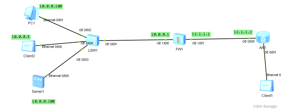
黑洞路由的几种应用场景
第一种在内网中产生环路: 这种核心交换机上肯定写一条默认路由 0.0.0.0 0 10.0.0.1 出口路由要写一条192.168.0.0 16 10.0.0.2 如果出口路由访问一条不存在的内网网段,又或者访问的那台终端停机了,那就会产生三层环路,数据包在…...
)
数据分析:智能企业七步曲(一)
原创: MicroStrategy微策略中国 作者:数据杰论 时间走到2018年最后一个季度,过去几年热炒的大数据概念正在各行各业开始落地并展开实际应用,核心是关注数据如何能为企业带来价值。因此,数据分析及其种种实现手段不断被…...

Django ModelSerializer 实现自定义验证详解
随着 Web 开发的日益复杂化,对数据验证的需求也日益增加。Django REST framework 提供了一套强大的、灵活的验证系统,帮助开发者轻松处理各种复杂情况。本文将重点探讨 Django ModelSerializer 中如何实现自定义验证。 1. 简介 Django ModelSerializer…...
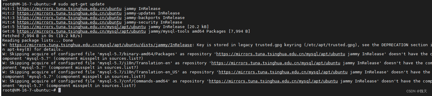
在ubuntu sudo apt-get update 更新报错
sudo apt-get update 更新报错 解决办法: 用你自己的key 根据上图自己找 sudo gpg --keyserver keyserver.ubuntu.com --recv-keys **********运行完成有一个ok 见下图 运行命令,中间的还是上面的key复制下来即可 sudo gpg --export --armor **********…...
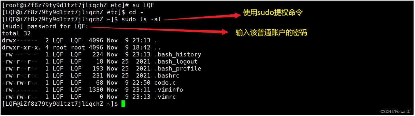
Linux——手把手教你解决sudo指令无法使用的问题
解决sudo指令无法使用的问题 1. 为什么不能使用 sudo指令能够使某一条指令拥有root权限,即以root权限去执行 例如: sudo ls -l //就是以root权限查看当前目录里的内容但是,如果是新创建的普通账户,一般来说一开始是不能执行s…...
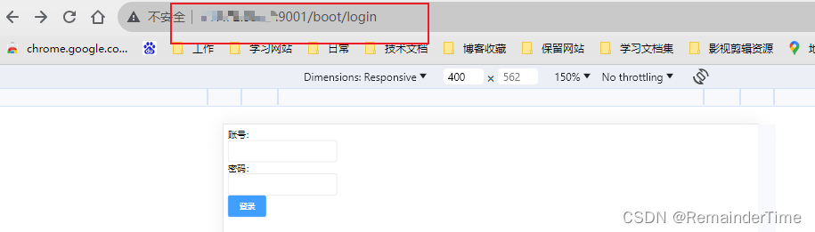
【云原生】使用nginx反向代理后台多服务器
背景 随着业务发展, 用户访问量激增,单台服务器已经无法满足现有的访问压力,研究后需要将后台服务从原来的单台升级为多台服务器,那么原来的访问方式无法满足,所以引入nginx来代理多台服务器,统一请求入口…...
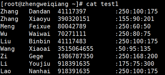
Linux awk命令
除了使用 sed 命令,Linux 系统中还有一个功能更加强大的文本数据处理工具,就是 awk。 曾有人推测 awk 命令的名字来源于 awkward 这个单词。其实不然,此命令的设计者有 3 位,他们的姓分别是 Aho、Weingberger 和 Kernighan&#x…...

南大通用数据库-Gbase-8a-学习-42-定位与释放锁
目录 一、测试版本 二、模拟锁表场景 1、查看自动提交参数 2、关闭自动提交 3、测试表结构 4、测试数据 5、会话一更新数据不提交 6、会话二更新数据卡住 7、会话三查看连接信息 8、会话三查看锁信息 9、解决方法 10、会话一插入数据不提交 11、会话二更新报错 三…...

css绘制常见的一些图形
以下是在CSS中绘制常见图形的示例代码: 线条: .line {width: 100px;height: 1px;background-color: black; }箭头: .arrow {width: 0;height: 0;border-top: 10px solid transparent;border-bottom: 10px solid transparent;border-right:…...
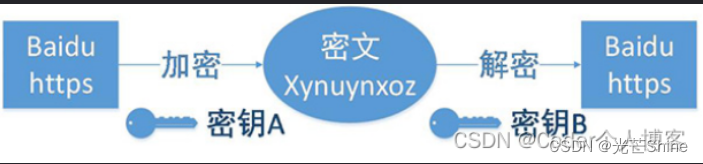
【网络协议】
网络协议 1 网络通讯1.1 防火墙1.2 子网掩码1.3 网关1.4 2 SSH2.1 SSH2.2 SSH12.3 SSH2 3 Telnet4 Telnet/SSL5 NFS6 TFTP7 FTP8 SFTP9 HTTP10 HTTPS11 NAT12 加密 1 网络通讯 1.1 防火墙 所谓“防火墙”,是指一种将内部网和公众访问网(如Internet)分开的方法&…...
如何在JVS低代码表单配置中实现数据的高效管理?
在数字化时代,表单已经成为企业、机构和个人收集、整理、分析数据的重要工具。然而,随着数据复杂性的增长,传统的单一表单往往难以满足需求。JVS低代码表单引擎中子表格允许在主表单中嵌套另一个子表数据,使得数据的收集和组织更加…...
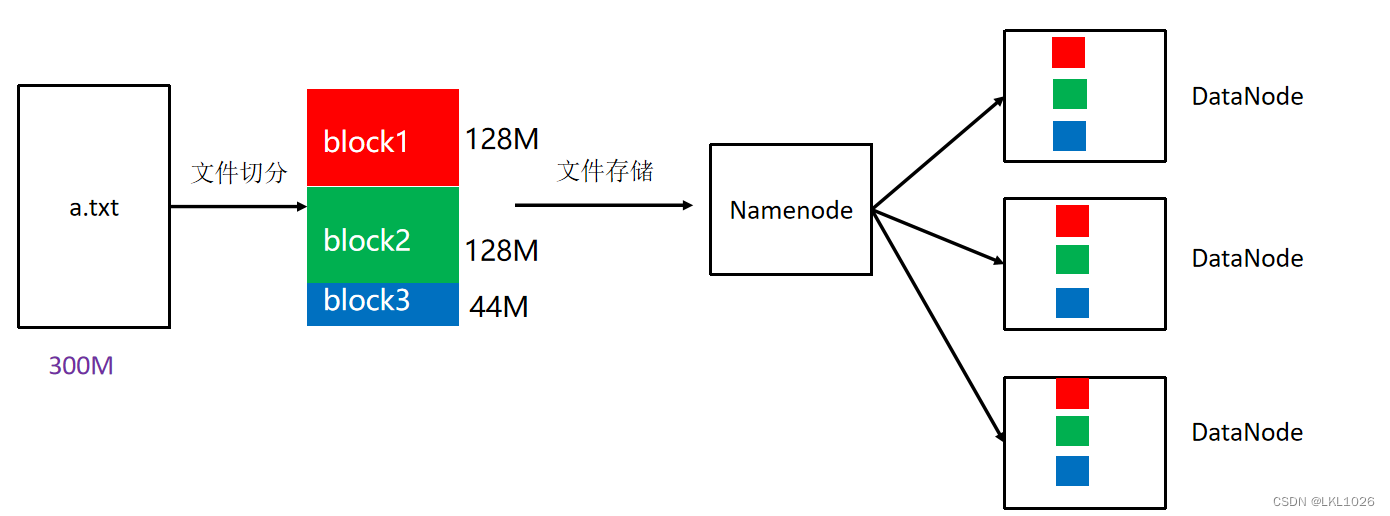
【Python大数据笔记_day04_Hadoop】
分布式和集群 分布式:多台服务器协同配合完成同一个大任务(每个服务器都只完成大任务拆分出来的单独1个子任务) 集群:多台服务器联合起来独立做相同的任务(多个服务器分担客户发来的请求) 注意:集群如果客户端请求量(任务量)多,多个服务器同时处理不同请求(不同任务),如果请求量…...

Android超简单的显示网络图片方法
Android显示网络图片的方法如下: 1、首先,需要在AndroidManifest.xml文件中添加网络权限: <uses-permission android:name"android.permission.INTERNET" /> 2、在布局文件中添加ImageView控件: <ImageVie…...

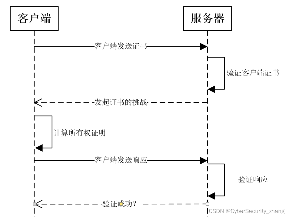
基于自然语言处理的结构化数据库问答机器人系统
温馨提示:文末有 CSDN 平台官方提供的学长 Wechat / QQ 名片 :) 1. 项目简介 知识库,就是人们总结出的一些历史知识的集合,存储、索引以后,可以被方便的检索出来供后人查询/学习。QnA Maker是用于建立知识库的工具,使用…...
JVM Native内存泄露的排查分析(64M 问题)
我们有一个线上的项目,刚启动完就占用了使用 top 命令查看 RES 占用了超过 1.5G,这明显不合理,于是进行了一些分析找到了根本的原因,下面是完整的分析过程,希望对你有所帮助。 会涉及到下面这些内容 Linux 经典的 64M…...
智能网联汽车基础软件信息安全需求分析
目录 1.安全启动 2.安全升级 3.安全存储 4.安全通信 5.安全调试 6.安全诊断 7.小结 1.安全启动 对于MCU,安全启动主要是以安全岛BootROM为信任根,在MCU启动后,用户程序运行前,硬件加密模块采用逐级校验、并行校验或者混合校…...
)
告别虚拟机!用A-Shell在iPad上搭建Python渗透学习环境(含SQLmap、Wafw00f等工具)
在iPad上构建移动端Python安全实验室:A-Shell实战指南 当iPad Pro配上妙控键盘的那一刻,很多人意识到这台设备完全可以替代传统笔记本电脑完成大部分工作。但对于网络安全学习者来说,似乎总缺了点什么——一个可以随时实践渗透测试工具的环境…...

告别BlueZ 4.x时代:为什么你的蓝牙音响连不上?详解BlueZ 5与PulseAudio的协作原理
蓝牙音频技术演进:从BlueZ 4.x到现代音频栈的架构变革 在嵌入式Linux开发中,蓝牙音频连接问题一直是个令人头疼的"玄学"问题。许多开发者都有过这样的经历:明明昨天还能正常工作的蓝牙音响,今天突然就无法连接了&#x…...

从零开始玩转Arduino:开源开发工具带你轻松进入硬件世界
从零开始玩转Arduino:开源开发工具带你轻松进入硬件世界 【免费下载链接】Arduino Arduino IDE 1.x 项目地址: https://gitcode.com/gh_mirrors/ar/Arduino 想象一下,你有一个创意想法,想要让LED灯随着音乐节奏闪烁,或者制…...

给爸妈手机装个Skype吧:一个账号搞定跨境/长途通话,操作比微信还简单
给父母手机装Skype:跨境通话的极简解决方案 当远隔重洋的视频通话成为日常,我们却常常忽略了一个更基础的需求——清晰稳定的语音沟通。许多海外游子发现,教会父母使用微信视频后,老人依然会下意识按下红色挂断键,只因…...

别再死记硬背Fama-French模型了!用Python实战带你搞懂因子投资的核心逻辑
用Python实战拆解Fama-French三因子模型:从数据获取到策略回测全流程 在量化投资的工具箱里,Fama-French三因子模型就像瑞士军刀般经典。但大多数教程要么停留在理论推导,要么给出黑箱代码。本文将用Jupyter Notebook逐行演示如何用Python实现…...

从PCB Layout到负载电容计算:手把手教你搞定25MHz以太网PHY晶振电路设计
25MHz以太网PHY晶振电路设计实战:从理论计算到PCB布局的完整指南 在工业通信和车载以太网系统中,25MHz晶振电路的稳定性直接决定了整个网络的传输质量。我曾在一个智能工厂项目中遇到过这样的案例:由于晶振负载电容计算偏差导致PHY芯片时钟漂…...

DevEco Studio报错后,项目目录里多了一堆.map和.js文件?别慌,用这个插件一键清理ArkTS缓存
DevEco Studio缓存文件异常?ArkTS编译残留文件高效清理指南 遇到DevEco Studio报错后项目目录突然出现大量.map和.js文件,这可能是ArkTS编译过程中产生的临时文件残留。这些文件不仅占用空间,还可能导致项目无法正常运行。本文将带你快速识别…...

1篇3章9节:搭建本地AI知识库,Obsidian + DripSick
在过去的几年里,AI工具如雨后春笋般出现,从ChatGPT到Claude、Gemini,再到各种嵌入式AI助手,写作、编程、办公、教学的方式正被悄然改变。而在众多AI使用场景中,有一个应用方式正在悄悄走红,那就是——本地知识库。简单来说,本地知识库就像是你的“数字大脑”。你把所有的…...

如何快速解决Windows热键冲突:Hotkey Detective智能检测工具完全指南
如何快速解决Windows热键冲突:Hotkey Detective智能检测工具完全指南 【免费下载链接】hotkey-detective A small program for investigating stolen key combinations under Windows 7 and later. 项目地址: https://gitcode.com/gh_mirrors/ho/hotkey-detective…...

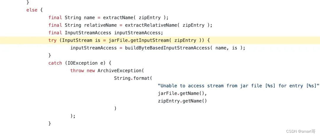
银行内网系统如何确保Excel公式导入CKEditor的数据安全?
CMS企业官网项目 - 编辑器Word导入功能集成记录 需求分析 作为四川的一名PHP程序员,最近接手的CMS企业官网项目客户提出了一个新需求:在CKEditor 4编辑器中实现Word等文档的一键导入功能。具体要求包括: 支持Word/Excel/PPT/PDF文档导入支…...