中断:Zynq Uart中断的流程和例程~UG585的CH.19
Zynq里的uart
UART 控制器是全双工异步接收器和发送器,支持多种可编程波特率和 I/O 信号格式。该控制器可以适应自动奇偶校验生成和多主机检测模式。
UART 操作由配置和模式寄存器控制。使用状态、中断状态和调制解调器状态寄存器读取 FIFO、调制解调器信号和其他控制器功能的状态。
该控制器采用独立的 Rx 和 Tx 数据路径构建。每条路径均包含一个 64 字节 FIFO。
该控制器对 Tx 和 Rx FIFO 中的数据进行串行化和反串行化,并包含一个模式开关以支持 RxD 和 TxD 信号的各种环回配置。 FIFO 中断状态位支持轮询或中断驱动的处理程序。软件使用 Rx 和 Tx 数据端口寄存器读取和写入数据字节。
(XUARTPS_IXR_RXOVR灯中断敏感事件就是在这里使用的)
当 UART 用于类似调制解调器的应用时,调制解调器控制模块会检测并生成调制解调器握手信号,并根据握手协议控制接收器和发送器路径。
TxFIFO和RXFIFO
TxFIFO
(机翻原文,此处涉及到一些UART的触发方法)
发送 FIFO (TxFIFO) 存储从 APB 接口写入的数据,直到该数据被发送模块移除并加载到其移位寄存器中。 TxFIFO 的最大数据宽度为 8 位。
通过写入 TxFIFO 寄存器将数据加载到 TxFIFO 中。
当数据加载到 TxFIFO 中时,TxFIFO 空标志被清除并保持在该低电平状态,直到 TxFIFO 中的最后一个字被移除并加载到发送器移位寄存器中。这意味着主机软件在需要下一个数据之前还有另一个完整的串行字时间,使其能够对设置的空标志做出反应,并在 TxFIFO 中写入另一个字,而不会损失传输时间。
TxFIFO 满中断状态 (TFULL) 指示 TxFIFO 已完全满,并阻止任何进一步的数据加载到 TxFIFO 中。如果对 TxFIFO 执行另一次 APB 写入,则会触发溢出,并且写入数据不会加载到 TxFIFO 中。发送 FIFO 几乎已满标志 (TNFULL) 表示 FIFO 中没有足够的可用空间,无法再写入一次编程大小(由模式寄存器的 WSIZE 位控制)。
TxFIFO 近满标志 (TNFULL) 指示 TxFIFO 中仅存在空闲字节。
可以在 TxFIFO 填充水平上设置阈值触发器 (TTRIG)。发送器触发寄存器可用于设置该值,以便在 TxFIFO 填充水平达到该编程值时设置触发。
RxFIFO
RxFIFO 存储接收器串行移位寄存器接收到的数据。 RxFIFO 的最大数据宽度为 8 位。
当数据加载到 RxFIFO 时,RxFIFO 空标志被清除,并且该状态保持低电平,直到 RxFIFO 中的所有数据都已通过 APB 接口传输。从空 RxFIFO 读取返回零。
RxFIFO 满状态(Chnl_int_sts_reg0 [RFUL] 和 Channel_sts_reg0 [RFUL] 位)指示 RxFIFO 已满,并阻止任何进一步的数据加载到 RxFIFO 中。当 RxFIFO 中出现可用空间时,将加载接收器中存储的任何字符。
可以在 RxFIFO 填充级别上设置阈值触发器 (RTRIG)。接收器触发电平寄存器 (Rcvr_FIFO_trigger_level0) 可用于设置该值,以便当 RxFIFO 填充电平转变为该编程值时设置触发。范围是 1 到 63。
当设置了缓冲区的时候,Rcvr_FIFO_trigger_level0的数值将会在缓冲区填满以后才开始计算,这会影响中断:
例如函数:XUartPs_SetFifoThreshold:
因为FIFO内的数值会被不断移出,填入缓冲区里。
可参考:
PYNQ UART控制器(二)库函数使用 轮询和中断两种方式使用_xuartps_send-CSDN博客
ZYNQ之UART中断实验软件设计-CSDN博客
初始化Uart
int  Uart_init(){int Status;Uart_ConFig = XUartPs_LookupConfig(UART_DEVICE_ID);if (NULL == Uart_ConFig) {return XST_FAILURE;}Status = XUartPs_CfgInitialize(&Uart_instance_point, Uart_ConFig, Uart_ConFig->BaseAddress);if (Status != XST_SUCCESS) {return XST_FAILURE;}Status = XUartPs_SelfTest(&Uart_instance_point);if (Status != XST_SUCCESS) {return XST_FAILURE;}Status = XUartPs_SetBaudRate(&Uart_instance_point,115200);if (Status != XST_SUCCESS) {return XST_UART_BAUD_ERROR;}
}
波特率
波特率发生器为接收器和发送器提供位周期时钟或波特率时钟。波特率时钟是通过分配基础时钟uart_clk和单周期时钟使能来实现的,以达到适当分频计时的效果。波特率生成的有效逻辑如图 19-3 所示。

波特率发生器可以使用主时钟信号 uart_ref_clk 或除以 8 的主时钟 uart_ref_clk/8。根据模式寄存器 (uart.mode_reg0) 中 CLKS 位的值选择使用的时钟信号。在下面的描述中,所得到的选定时钟被称为 sel_clk。
sel_clk 时钟被分频以生成其他三个时钟:baud_sample、baud_tx_rate 和 baud_rx_rate。 baud_tx_rate 是用于传输数据的目标波特率。 baud_rx_rate 名义上具有相同的速率,但会与传入的接收数据重新同步。 baud_sample 以 baud_rx_rate 和 baud_tx_rate 的倍数 ([BDIV] + 1) 运行,用于对接收的数据进行过采样。
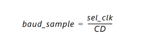
sel_clk 时钟频率除以波特率发生器寄存器中的 CD 字段值,以生成 baud_sample 时钟使能。该寄存器可以编程为 1 到 65535 之间的值。
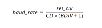
baud_sample 时钟除以 [BDIV] 加 1。BDIV 是波特率分频寄存器中的一个可编程字段,可以编程为 4 到 255 之间的值。它的复位值为 15,推断默认比率为 16 baud_sample每个 baud_tx_clock / baud_rx_rate 的时钟。
因此,baud_sample 时钟使能的频率如公式 19-1 所示。
baud_rx_rate 和 baud_tx_rate 时钟使能的频率如公式 19-2 所示。
为Uart 配置中断函数相关
int Uart_SetHandler_Event(){u32 IntrMask = 0;int Index;XUartPs_SetHandler(&Uart_instance_point,(XUartPs_Handler)Uart0_IntrHandler,&Uart_instance_point);IntrMask =XUARTPS_IXR_TOUT | XUARTPS_IXR_PARITY | XUARTPS_IXR_FRAMING |XUARTPS_IXR_OVER | XUARTPS_IXR_TXEMPTY | XUARTPS_IXR_RXFULL |XUARTPS_IXR_RXOVR;XUartPs_SetInterruptMask(&Uart_instance_point, IntrMask);XUartPs_SetOperMode(&Uart_instance_point,XUARTPS_OPER_MODE_NORMAL);XUartPs_SetRecvTimeout(&Uart_instance_point,8);for (Index = 0; Index < TEST_BUFFER_SIZE; Index++) {// SendBuffer[Index] = (Index % 26) + 'A';RecvBuffer[Index] = 0;}XUartPs_Recv(&Uart_instance_point, RecvBuffer, TEST_BUFFER_SIZE);XUartPs_Send(&Uart_instance_point, SendBuffer, TEST_BUFFER_SIZE);
}
包含:
中断函数设置;
设置敏感事件列表;
设置操作模式;
设置超时(非必须);
设置收发监视。
中断函数设置
XUartPs_SetHandler(UartInstPtr, (XUartPs_Handler)Handler, UartInstPtr);void XUartPs_SetHandler(XUartPs *InstancePtr, XUartPs_Handler FuncPtr, void *CallBackRef)Uart中断函数的规范
void Handler(void *CallBackRef, u32 Event, EventData)
这里对于Event:处理程序事件有严格约束。
/******************************************************** *************************/
/** *
* 该函数是执行处理以处理来自设备的数据事件的处理程序。它是从中断上下文中调用的。所以
* 处理量应该是最小的。
* * 该处理程序提供了如何处理设备数据的示例,并且
* 是特定于应用程序的。
* * @param CallBackRef 包含来自驱动程序的回调引用,
* 在本例中它是 XUartPs 驱动程序的实例指针。
* @param Event 包含已发生的特定类型的事件。
* @param EventData 包含发送和接收事件发送或接收的字节数。
* * @返回无。
* * @note 无。
********************************************************* **************************/
注册Uart处理程序事件
u32 Event:当触发中断的时候,根据不同事件来决定编程好的操作。
EventData:不同的事件有不同的数据。大体指的是触发指定事件时,发送和接收事件发送或接收的字节数。
EventData
例如:通过存储这部分字节数并且编程来判断是否出现问题。
/* 数据全部发送完毕 *//* All of the data has been sent */if (Event == XUARTPS_EVENT_SENT_DATA) {TotalSentCount = EventData;} /** 收到数据,但不是预期的字节数,* 超时仅表示数据停止了 8 个字符时间*//** Data was received, but not the expected number of bytes, a* timeout just indicates the data stopped for 8 character times*/if (Event == XUARTPS_EVENT_RECV_TOUT) {TotalReceivedCount = EventData;}事件列表:
/** @name Callback events** These constants specify the handler events that an application can handle* using its specific handler function. Note that these constants are not bit* mask, so only one event can be passed to an application at a time.* 这些常量指定应用程序可以使用其特定处理程序函数处理的处理程序事件。请注意,这些常量不是位 * 掩码,因此一次只能将一个事件传递到应用程序。** @{*/
#define XUARTPS_EVENT_RECV_DATA			1U /**< Data receiving done */
#define XUARTPS_EVENT_RECV_TOUT			2U /**< A receive timeout occurred */
#define XUARTPS_EVENT_SENT_DATA			3U /**< Data transmission done */
#define XUARTPS_EVENT_RECV_ERROR		4U /**< A receive error detected */
#define XUARTPS_EVENT_MODEM				5U /**< Modem status changed */
#define XUARTPS_EVENT_PARE_FRAME_BRKE	6U /**< A receive parity, frame, break*	error detected */
#define XUARTPS_EVENT_RECV_ORERR		7U /**< A receive overrun error detected */
Uart中断函数范例
/**************************************************************************/
/**
*
* This function is the handler which performs processing to handle data events
* from the device.  It is called from an interrupt context. so the amount of
* processing should be minimal.
*
* This handler provides an example of how to handle data for the device and
* is application specific.
*
* @param	CallBackRef contains a callback reference from the driver,
*		in this case it is the instance pointer for the XUartPs driver.
* @param	Event contains the specific kind of event that has occurred.
* @param	EventData contains the number of bytes sent or received for sent
*		and receive events.
*
* @return	None.
*
* @note		None.
*
***************************************************************************/
void Handler(void *CallBackRef, u32 Event, unsigned int EventData)
{/* 数据全部发送完毕 *//* All of the data has been sent */if (Event == XUARTPS_EVENT_SENT_DATA) {TotalSentCount = EventData;}/* 全部数据已接收 *//* All of the data has been received */if (Event == XUARTPS_EVENT_RECV_DATA) {TotalReceivedCount = EventData;}/* * 收到数据,但不是预期的字节数, * 超时仅表示数据停止了 8 个字符时间 *//** Data was received, but not the expected number of bytes, a* timeout just indicates the data stopped for 8 character times*/if (Event == XUARTPS_EVENT_RECV_TOUT) {TotalReceivedCount = EventData;}/* * 接收到的数据有错误,保留数据但确定 * 发生了什么类型的错误 *//** Data was received with an error, keep the data but determine* what kind of errors occurred*/if (Event == XUARTPS_EVENT_RECV_ERROR) {TotalReceivedCount = EventData;TotalErrorCount++;}/* * 收到的数据带有奇偶校验或帧或中断错误,保留数据 * 但确定发生了哪种错误。特定于 Zynq     Ultrascale+ * MP。*//** Data was received with an parity or frame or break error, keep the data* but determine what kind of errors occurred. Specific to Zynq Ultrascale+* MP.*/if (Event == XUARTPS_EVENT_PARE_FRAME_BRKE) {TotalReceivedCount = EventData;TotalErrorCount++;}/* * 收到数据时出现溢出错误,保留数据但确定 * 发生了哪种错误。特定于 Zynq Ultrascale+ MP。*//** Data was received with an overrun error, keep the data but determine* what kind of errors occurred. Specific to Zynq Ultrascale+ MP.*/if (Event == XUARTPS_EVENT_RECV_ORERR) {TotalReceivedCount = EventData;TotalErrorCount++;}
}
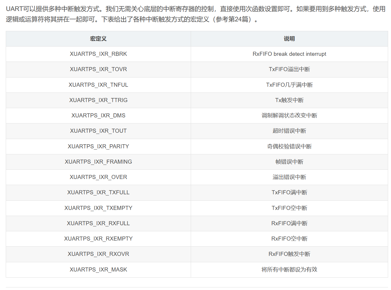
为UART 设置触发触发方式掩码(敏感列表):XUartPs_SetInterruptMask
即中断的敏感列表。
void XUartPs_SetInterruptMask(XUartPs *InstancePtr, u32 Mask)
该函数设置中断掩码。
参数:
InstancePtr – 是指向 XUartPs 实例的指针
Mask – 包含要启用或禁用的中断。 “1”启用中断,“0”禁用中断。
IntrMask =XUARTPS_IXR_TOUT | XUARTPS_IXR_PARITY | XUARTPS_IXR_FRAMING |XUARTPS_IXR_OVER | XUARTPS_IXR_TXEMPTY | XUARTPS_IXR_RXFULL |XUARTPS_IXR_RXOVR;if (UartInstPtr->Platform == XPLAT_ZYNQ_ULTRA_MP) {IntrMask |= XUARTPS_IXR_RBRK;}XUartPs_SetInterruptMask(UartInstPtr, IntrMask);
中断方式的介绍:(部分)
ug585 P595
Receiver Parity Error:XUARTPS_IXR_PARITY
每次接收到字符时,接收器都会根据 uart.mode_reg0 [PAR] 位字段计算接收到的数据位的奇偶校验。然后将结果与接收到的奇偶校验位进行比较。
如果检测到差异,则奇偶校验错误位设置为 = 1,uart.Chnl_int_sts_reg0 [PARE]。如果启用,则会生成中断。
Receiver Framing Error:XUARTPS_IXR_FRAMING
接收器帧错误 当接收器未能在帧末尾接收到有效停止位时,
帧错误位设置为 =1,uart.Chnl_int_sts_reg0 [FRAME]。如果启用,则会生成中断。
Receiver Overflow Error:XUARTPS_IXR_RXFULL
当接收到字符时,控制器检查 RxFIFO 是否有空间。
如果是,则该字符被写入 RxFIFO。
如果 RxFIFO 已满,则控制器等待。
如果检测到 RxD 上的后续起始位且 RxFIFO 仍满,则数据会丢失,控制器会设置 Rx 溢出中断位 uart.Chnl_int_sts_reg0 [ROVR] = 1。如果启用,则会生成中断。
Receiver Timeout Mechanism:XUARTPS_IXR_TOUT
接收器超时机制:使接收器能够检测非活动 RxD 信号(持续高电平)。超时周期通过写入 uart.Rcvr_timeout_reg0 [RTO] 位字段来编程。超时机制使用10位递减计数器。每当在 RxD 信号上接收到新的起始位,或每当软件将 1 写入 uart.Control_reg0 [RSTTO](无论之前的 [RSTTO] 值如何)时,计数器都会重新加载并开始递减计数。
如果在 1,023 位周期内没有发生起始位或复位超时,则发生超时。
接收器超时错误位[TIMEOUT]将在中断状态寄存器中设置,并且控制寄存器中的[RSTTO]位应写入1以重新启动超时计数器,从而加载新编程的超时值。
计数器的高 8 位从 [RTO] 位字段中的值重新加载,低 2 位初始化为零。计数器由 UART 位时钟提供时钟。
例如,如果 [RTO] = 0xFF,则超时周期为 1,023 位时钟(256 x 4 减 1)。如果[RTO]位写入0,则超时机制被禁用。
当递减计数器达到 0 时,接收器超时发生,控制器设置超时中断状态位 uart.Chnl_int_sts_reg0 [TIMEOUT] = 1。
如果中断使能(uart.Intrpt_mask_reg0 [TIMEOUT] = 1),则 IRQ 信号PS 中断控制器被置位。
每当发生超时中断时,都会通过向 Chnl_int_sts_reg0 [TIMEOUT] 位回写 1 来清除该中断。
软件必须设置 uart.Control_reg0 [RSTTO] = 1 以生成进一步的接收超时中断。
/*
* @name 中断寄存器
*
* 中断控制逻辑使用中断允许寄存器(IER)和
* 中断禁止寄存器(IDR)来设置
* 中断屏蔽寄存器(IMR)中的位的值。 IMR 确定是否将
* 中断传递给中断状态寄存器(ISR)。
* 向 IER 写入 1 启用中断,向 IDR 写入 1 禁用
* 中断。 IMR 和 ISR 是只读的,IER 和 IDR 是只写的。
* 读取 IER 或 IDR 返回 0x00。
* * 所有四个寄存器具有相同的位定义。
* * @{ */
*/
#define XUARTPS_IXR_RBRK 0x00002000U /**< Rx FIFO break detect interrupt */
#define XUARTPS_IXR_TOVR 0x00001000U /**< Tx FIFO Overflow interrupt */
#define XUARTPS_IXR_TNFUL 0x00000800U /**< Tx FIFO Nearly Full interrupt */
#define XUARTPS_IXR_TTRIG 0x00000400U /**< Tx Trig interrupt */
#define XUARTPS_IXR_DMS 0x00000200U /**< Modem status change interrupt */
#define XUARTPS_IXR_TOUT 0x00000100U /**< Timeout error interrupt */
#define XUARTPS_IXR_PARITY 0x00000080U /**< Parity error interrupt */
#define XUARTPS_IXR_FRAMING 0x00000040U /**< Framing error interrupt */
#define XUARTPS_IXR_OVER 0x00000020U /**< Overrun error interrupt */
#define XUARTPS_IXR_TXFULL 0x00000010U /**< TX FIFO full interrupt. */
#define XUARTPS_IXR_TXEMPTY 0x00000008U /**< TX FIFO empty interrupt. */
#define XUARTPS_IXR_RXFULL 0x00000004U /**< RX FIFO full interrupt. */
#define XUARTPS_IXR_RXEMPTY 0x00000002U /**< RX FIFO empty interrupt. */
#define XUARTPS_IXR_RXOVR 0x00000001U /**< RX FIFO trigger interrupt. */
#define XUARTPS_IXR_MASK 0x00003FFFU /**< Valid bit mask */
/* @} */学会Zynq(27)UART中断驱动模式示例-CSDN博客
为UART 设置操作模式

控制逻辑包含控制寄存器和模式寄存器,用于选择UART的各种工作模式。
控制寄存器启用、禁用接收器和发送器模块并发出软复位。 此外,它还重新启动接收器超时周期,并控制发送器中断逻辑。
接收断线检测必须在软件中实现。它将由 RxFIFO 中的一个帧错误后跟一个或多个零字节来指示。模式寄存器选择波特率发生器使用的时钟。它还选择发送和接收数据所使用的位长度、奇偶校验位和停止位。此外,它还可以选择 UART 的操作模式,根据需要在正常 UART 模式、自动回显、本地环回或远程环回之间切换。
void XUartPs_SetOperMode(XUartPs *InstancePtr, u8 OperationMode)
该函数设置 UART 的操作模式。
UART 可以在四种模式之一下运行:
正常、本地环回、远程环回或自动回显。
参数: InstancePtr – 是指向 XUartPs 实例的指针。
操作模式 – 是 UART 的模式。
Normal, Local Loopback, Remote Loopback, or automatic echo.
#define XUARTPS_OPER_MODE_NORMAL		(u8)0x00U	/**< Normal Mode */
#define XUARTPS_OPER_MODE_AUTO_ECHO		(u8)0x01U	/**< Auto Echo Mode */
#define XUARTPS_OPER_MODE_LOCAL_LOOP	(u8)0x02U	/**< Local Loopback Mode */
#define XUARTPS_OPER_MODE_REMOTE_LOOP	(u8)0x03U	/**< Remote Loopback Mode */XUartPs_SetOperMode(UartInstPtr, XUARTPS_OPER_MODE_LOCAL_LOOP);
根据设置的敏感事件(触发方式)使用函数
上文中可知有许多敏感事件可用。
如果我们使用的是:XUartPs_SetInterruptMask(Uart_Ps, XUARTPS_IXR_RXOVR);
则可以通过使用:来设置具体的触发等级。
void XUartPs_SetFifoThreshold(XUartPs *InstancePtr, u8 TriggerLevel)
//RxFIFO中的字节数超过TriggerLevel时,会产生一个接收数据中断。不设置的时候默认为8.
取值应在1~64,因为RxFIFO最大只能存储64个字节。
The controller is structured with separate Rx and Tx data paths. Each path includes a 64-byte FIFO.
设置 UART 的接收超时
void XUartPs_SetRecvTimeout(XUartPs *InstancePtr, u8 RecvTimeout)
RecvTimeout:超时字符时间
设置允许 UART 检测接收器数据线上的空闲连接。
超时持续时间 = RecvTimeout x 4 x 位周期。 0 禁用超时功能。
超过RecvTimeout时,视为超时,发生中断。
可以设置其他的,例如:
XUartPs_SetInterruptMask(Uart_Ps, XUARTPS_IXR_RXOVR);
RxFIFO触发中断:
/**
*
* 该函数设置UART的接收超时。
*
* @param InstancePtr 是指向 XUartPs 实例的指针。
* @param RecvTimeout 设置允许 UART 检测接收器数据线上的空闲连接。
* 超时持续时间 = RecvTimeout x 4 x 位周期。 0 禁用
* 超时功能。
*
* @返回无。
/*
* 设置接收器超时。如果不设置,并且数据的最后几个字节
* 没有触发过水或满中断,则不会接收该字节
*。默认情况下它是禁用的。
*
* 设置为 8 将在 8 x 4 = 32 个字符时间后超时。
* 如果波特率高,则增加超时值;如果
* 波特率低,则减少超时值。
*//****************************************************************************/
/**
*
* This function sets the Receive Timeout of the UART.
*
* @param InstancePtr is a pointer to the XUartPs instance.
* @param RecvTimeout setting allows the UART to detect an idle connection
* on the receiver data line.
* Timeout duration = RecvTimeout x 4 x Bit Period. 0 disables the
* timeout function.
*
* @return None.
*
* @note None.
*
*****************************************************************************/
void XUartPs_SetRecvTimeout(XUartPs *InstancePtr, u8 RecvTimeout)
{u32 RtoRegister;/* Assert validates the input arguments */Xil_AssertVoid(InstancePtr != NULL);Xil_AssertVoid(InstancePtr->IsReady == XIL_COMPONENT_IS_READY);/* Set the correct value by masking the bits */RtoRegister = ((u32)RecvTimeout & (u32)XUARTPS_RXTOUT_MASK);XUartPs_WriteReg(InstancePtr->Config.BaseAddress,XUARTPS_RXTOUT_OFFSET, RtoRegister);/* Configure CR to restart the receiver timeout counter */RtoRegister =XUartPs_ReadReg(InstancePtr->Config.BaseAddress,XUARTPS_CR_OFFSET);XUartPs_WriteReg(InstancePtr->Config.BaseAddress, XUARTPS_CR_OFFSET,(RtoRegister | XUARTPS_CR_TORST));}监听串口数据和初始化缓冲区
/*
* 在发送数据之前开始接收数据,因为存在环回,
* 忽略作为返回值接收到的字节数,因为我们
* 知道它将为零
*/
/** Start receiving data before sending it since there is a loopback,* ignoring the number of bytes received as the return value since we* know it will be zero*///Define Buffer#define TEST_BUFFER_SIZE 256static u8 SendBuffer[TEST_BUFFER_SIZE]; /* Buffer for Transmitting Data */static u8 RecvBuffer[TEST_BUFFER_SIZE]; /* Buffer for Receiving Data */XUartPs_Recv(UartInstPtr, RecvBuffer, TEST_BUFFER_SIZE);u32 XUartPs_Recv(XUartPs *InstancePtr, u8 *BufferPtr, u32 NumBytes) 该函数尝试从设备接收指定字节数的数据并将其存储到指定的缓冲区中。该函数适用于轮询或中断驱动模式。它是非阻塞的。在轮询模式下,该函数将仅接收 RX FIFO 中已有的数据。应用程序可能需要重复调用它才能接收整个缓冲区。轮询模式是设备的默认操作模式。在中断模式下,该函数将开始接收,如果没有接收到整个缓冲区,则中断处理程序将继续接收数据,直到接收到整个缓冲区。将调用应用程序指定的回调函数来指示接收完成或错误情况。
参数:
InstancePtr – 是指向 XUartPs 实例的指针
BufferPtr – 是指向要接收到数据的缓冲区的指针
NumBytes – 是要接收的字节数。
零值将停止之前在中断模式下正在进行的接收操作。初始化缓冲区:
/*
* 使用模式初始化发送缓冲区字节,
* 并将接收缓冲区字节初始化为零,以允许接收数据被验证
*/
根据自己的需求选择初始化情况。
for (Index = 0; Index < TEST_BUFFER_SIZE; Index++) {SendBuffer[Index] = (Index % 26) + 'A';RecvBuffer[Index] = 0;}整体例程:
/**************************************************************************/
/**
*
* This function does a minimal test on the UartPS device and driver as a
* design example. The purpose of this function is to illustrate
* how to use the XUartPs driver.
*
* This function sends data and expects to receive the same data through the
* device using the local loopback mode.
*
* This function uses interrupt mode of the device.
*
* @param	IntcInstPtr is a pointer to the instance of the Scu Gic driver.
* @param	UartInstPtr is a pointer to the instance of the UART driver
*		which is going to be connected to the interrupt controller.
* @param	DeviceId is the device Id of the UART device and is typically
*		XPAR_<UARTPS_instance>_DEVICE_ID value from xparameters.h.
* @param	UartIntrId is the interrupt Id and is typically
*		XPAR_<UARTPS_instance>_INTR value from xparameters.h.
*
* @return	XST_SUCCESS if successful, otherwise XST_FAILURE.
*
* @note
*
* This function contains an infinite loop such that if interrupts are not
* working it may never return.
*
**************************************************************************/
int UartPsIntrExample(INTC *IntcInstPtr, XUartPs *UartInstPtr,u16 DeviceId, u16 UartIntrId)
{int Status;XUartPs_Config *Config;int Index;u32 IntrMask;int BadByteCount = 0;#ifndef TESTAPP_GENif (XGetPlatform_Info() == XPLAT_ZYNQ_ULTRA_MP) {
#ifdef XPAR_XUARTPS_1_DEVICE_IDDeviceId = XPAR_XUARTPS_1_DEVICE_ID;
#endif}
#endif/** Initialize the UART driver so that it's ready to use* Look up the configuration in the config table, then initialize it.*/Config = XUartPs_LookupConfig(DeviceId);if (NULL == Config) {return XST_FAILURE;}Status = XUartPs_CfgInitialize(UartInstPtr, Config, Config->BaseAddress);if (Status != XST_SUCCESS) {return XST_FAILURE;}/* Check hardware build */Status = XUartPs_SelfTest(UartInstPtr);if (Status != XST_SUCCESS) {return XST_FAILURE;}/** Connect the UART to the interrupt subsystem such that interrupts* can occur. This function is application specific.*/Status = SetupInterruptSystem(IntcInstPtr, UartInstPtr, UartIntrId);if (Status != XST_SUCCESS) {return XST_FAILURE;}/** Setup the handlers for the UART that will be called from the* interrupt context when data has been sent and received, specify* a pointer to the UART driver instance as the callback reference* so the handlers are able to access the instance data*/XUartPs_SetHandler(UartInstPtr, (XUartPs_Handler)Handler, UartInstPtr);/** Enable the interrupt of the UART so interrupts will occur, setup* a local loopback so data that is sent will be received.*/IntrMask =XUARTPS_IXR_TOUT | XUARTPS_IXR_PARITY | XUARTPS_IXR_FRAMING |XUARTPS_IXR_OVER | XUARTPS_IXR_TXEMPTY | XUARTPS_IXR_RXFULL |XUARTPS_IXR_RXOVR;if (UartInstPtr->Platform == XPLAT_ZYNQ_ULTRA_MP) {IntrMask |= XUARTPS_IXR_RBRK;}XUartPs_SetInterruptMask(UartInstPtr, IntrMask);XUartPs_SetOperMode(UartInstPtr, XUARTPS_OPER_MODE_LOCAL_LOOP);/** Set the receiver timeout. If it is not set, and the last few bytes* of data do not trigger the over-water or full interrupt, the bytes* will not be received. By default it is disabled.** The setting of 8 will timeout after 8 x 4 = 32 character times.* Increase the time out value if baud rate is high, decrease it if* baud rate is low.*/XUartPs_SetRecvTimeout(UartInstPtr, 8);/** Initialize the send buffer bytes with a pattern and the* the receive buffer bytes to zero to allow the receive data to be* verified*/for (Index = 0; Index < TEST_BUFFER_SIZE; Index++) {SendBuffer[Index] = (Index % 26) + 'A';RecvBuffer[Index] = 0;}/** Start receiving data before sending it since there is a loopback,* ignoring the number of bytes received as the return value since we* know it will be zero*/XUartPs_Recv(UartInstPtr, RecvBuffer, TEST_BUFFER_SIZE);/** Send the buffer using the UART and ignore the number of bytes sent* as the return value since we are using it in interrupt mode.*/XUartPs_Send(UartInstPtr, SendBuffer, TEST_BUFFER_SIZE);/** Wait for the entire buffer to be received, letting the interrupt* processing work in the background, this function may get locked* up in this loop if the interrupts are not working correctly.*/while (1) {if ((TotalSentCount == TEST_BUFFER_SIZE) &&(TotalReceivedCount == TEST_BUFFER_SIZE)) {break;}}/* Verify the entire receive buffer was successfully received */for (Index = 0; Index < TEST_BUFFER_SIZE; Index++) {if (RecvBuffer[Index] != SendBuffer[Index]) {BadByteCount++;}}/* Set the UART in Normal Mode */XUartPs_SetOperMode(UartInstPtr, XUARTPS_OPER_MODE_NORMAL);/* If any bytes were not correct, return an error */if (BadByteCount != 0) {return XST_FAILURE;}return XST_SUCCESS;
}
/******************************************************************************
* Copyright (C) 2010 - 2021 Xilinx, Inc. All rights reserved.
* SPDX-License-Identifier: MIT
******************************************************************************//****************************************************************************/
/**
*
* @file xuartps_intr_example.c
*
* This file contains a design example using the XUartPs driver in interrupt
* mode. It sends data and expects to receive the same data through the device
* using the local loopback mode.
*
*
* @note
* The example contains an infinite loop such that if interrupts are not
* working it may hang.
*
* MODIFICATION HISTORY:
* <pre>
* Ver Who Date Changes
* ----- ------ -------- ----------------------------------------------
* 1.00a drg/jz 01/13/10 First Release
* 1.00a sdm 05/25/11 Modified the example for supporting Peripheral tests
* in SDK
* 1.03a sg 07/16/12 Updated the example for CR 666306. Modified
* the device ID to use the first Device Id
* and increased the receive timeout to 8
* Removed the printf at the start of the main
* Put the device normal mode at the end of the example
* 3.1 kvn 04/10/15 Added code to support Zynq Ultrascale+ MP.
* 3.1 mus 01/14/16 Added support for intc interrupt controller
* 3.8 adk 10/05/19 Don't update the DeviceId variable in peripheral test
* app case.
*
* </pre>
****************************************************************************//***************************** Include Files *******************************/#include "xparameters.h"
#include "xplatform_info.h"
#include "xuartps.h"
#include "xil_exception.h"
#include "xil_printf.h"#ifdef XPAR_INTC_0_DEVICE_ID
#include "xintc.h"
#else
#include "xscugic.h"
#endif
/************************** Constant Definitions **************************//** The following constants map to the XPAR parameters created in the* xparameters.h file. They are defined here such that a user can easily* change all the needed parameters in one place.*/
#ifdef XPAR_INTC_0_DEVICE_ID
#define INTC XIntc
#define UART_DEVICE_ID XPAR_XUARTPS_0_DEVICE_ID
#define INTC_DEVICE_ID XPAR_INTC_0_DEVICE_ID
#define UART_INT_IRQ_ID XPAR_INTC_0_UARTPS_0_VEC_ID
#else
#define INTC XScuGic
#define UART_DEVICE_ID XPAR_XUARTPS_0_DEVICE_ID
#define INTC_DEVICE_ID XPAR_SCUGIC_SINGLE_DEVICE_ID
#define UART_INT_IRQ_ID XPAR_XUARTPS_1_INTR
#endif
/** The following constant controls the length of the buffers to be sent* and received with the UART,*/
#define TEST_BUFFER_SIZE 100/**************************** Type Definitions ******************************//************************** Function Prototypes *****************************/int UartPsIntrExample(INTC *IntcInstPtr, XUartPs *UartInstPtr,u16 DeviceId, u16 UartIntrId);static int SetupInterruptSystem(INTC *IntcInstancePtr,XUartPs *UartInstancePtr,u16 UartIntrId);void Handler(void *CallBackRef, u32 Event, unsigned int EventData);/************************** Variable Definitions ***************************/XUartPs UartPs ; /* Instance of the UART Device */
INTC InterruptController; /* Instance of the Interrupt Controller *//** The following buffers are used in this example to send and receive data* with the UART.*/
static u8 SendBuffer[TEST_BUFFER_SIZE]; /* Buffer for Transmitting Data */
static u8 RecvBuffer[TEST_BUFFER_SIZE]; /* Buffer for Receiving Data *//** The following counters are used to determine when the entire buffer has* been sent and received.*/
volatile int TotalReceivedCount;
volatile int TotalSentCount;
int TotalErrorCount;/**************************************************************************/
/**
*
* Main function to call the Uart interrupt example.
*
*
* @return XST_SUCCESS if successful, XST_FAILURE if unsuccessful
*
* @note None
*
**************************************************************************/
#ifndef TESTAPP_GEN
int main(void)
{int Status;/* Run the UartPs Interrupt example, specify the the Device ID */Status = UartPsIntrExample(&InterruptController, &UartPs,UART_DEVICE_ID, UART_INT_IRQ_ID);if (Status != XST_SUCCESS) {xil_printf("UART Interrupt Example Test Failed\r\n");return XST_FAILURE;}xil_printf("Successfully ran UART Interrupt Example Test\r\n");return XST_SUCCESS;
}
#endif/**************************************************************************/
/**
*
* This function does a minimal test on the UartPS device and driver as a
* design example. The purpose of this function is to illustrate
* how to use the XUartPs driver.
*
* This function sends data and expects to receive the same data through the
* device using the local loopback mode.
*
* This function uses interrupt mode of the device.
*
* @param IntcInstPtr is a pointer to the instance of the Scu Gic driver.
* @param UartInstPtr is a pointer to the instance of the UART driver
* which is going to be connected to the interrupt controller.
* @param DeviceId is the device Id of the UART device and is typically
* XPAR_<UARTPS_instance>_DEVICE_ID value from xparameters.h.
* @param UartIntrId is the interrupt Id and is typically
* XPAR_<UARTPS_instance>_INTR value from xparameters.h.
*
* @return XST_SUCCESS if successful, otherwise XST_FAILURE.
*
* @note
*
* This function contains an infinite loop such that if interrupts are not
* working it may never return.
*
**************************************************************************/
int UartPsIntrExample(INTC *IntcInstPtr, XUartPs *UartInstPtr,u16 DeviceId, u16 UartIntrId)
{int Status;XUartPs_Config *Config;int Index;u32 IntrMask;int BadByteCount = 0;#ifndef TESTAPP_GENif (XGetPlatform_Info() == XPLAT_ZYNQ_ULTRA_MP) {
#ifdef XPAR_XUARTPS_1_DEVICE_IDDeviceId = XPAR_XUARTPS_1_DEVICE_ID;
#endif}
#endif/** Initialize the UART driver so that it's ready to use* Look up the configuration in the config table, then initialize it.*/Config = XUartPs_LookupConfig(DeviceId);if (NULL == Config) {return XST_FAILURE;}Status = XUartPs_CfgInitialize(UartInstPtr, Config, Config->BaseAddress);if (Status != XST_SUCCESS) {return XST_FAILURE;}/* Check hardware build */Status = XUartPs_SelfTest(UartInstPtr);if (Status != XST_SUCCESS) {return XST_FAILURE;}/** Connect the UART to the interrupt subsystem such that interrupts* can occur. This function is application specific.*/Status = SetupInterruptSystem(IntcInstPtr, UartInstPtr, UartIntrId);if (Status != XST_SUCCESS) {return XST_FAILURE;}/** Setup the handlers for the UART that will be called from the* interrupt context when data has been sent and received, specify* a pointer to the UART driver instance as the callback reference* so the handlers are able to access the instance data*/XUartPs_SetHandler(UartInstPtr, (XUartPs_Handler)Handler, UartInstPtr);/** Enable the interrupt of the UART so interrupts will occur, setup* a local loopback so data that is sent will be received.*/IntrMask =XUARTPS_IXR_TOUT | XUARTPS_IXR_PARITY | XUARTPS_IXR_FRAMING |XUARTPS_IXR_OVER | XUARTPS_IXR_TXEMPTY | XUARTPS_IXR_RXFULL |XUARTPS_IXR_RXOVR;if (UartInstPtr->Platform == XPLAT_ZYNQ_ULTRA_MP) {IntrMask |= XUARTPS_IXR_RBRK;}XUartPs_SetInterruptMask(UartInstPtr, IntrMask);XUartPs_SetOperMode(UartInstPtr, XUARTPS_OPER_MODE_LOCAL_LOOP);/** Set the receiver timeout. If it is not set, and the last few bytes* of data do not trigger the over-water or full interrupt, the bytes* will not be received. By default it is disabled.** The setting of 8 will timeout after 8 x 4 = 32 character times.* Increase the time out value if baud rate is high, decrease it if* baud rate is low.*/XUartPs_SetRecvTimeout(UartInstPtr, 8);/** Initialize the send buffer bytes with a pattern and the* the receive buffer bytes to zero to allow the receive data to be* verified*/for (Index = 0; Index < TEST_BUFFER_SIZE; Index++) {SendBuffer[Index] = (Index % 26) + 'A';RecvBuffer[Index] = 0;}/** Start receiving data before sending it since there is a loopback,* ignoring the number of bytes received as the return value since we* know it will be zero*/XUartPs_Recv(UartInstPtr, RecvBuffer, TEST_BUFFER_SIZE);/** Send the buffer using the UART and ignore the number of bytes sent* as the return value since we are using it in interrupt mode.*/XUartPs_Send(UartInstPtr, SendBuffer, TEST_BUFFER_SIZE);/** Wait for the entire buffer to be received, letting the interrupt* processing work in the background, this function may get locked* up in this loop if the interrupts are not working correctly.*/while (1) {if ((TotalSentCount == TEST_BUFFER_SIZE) &&(TotalReceivedCount == TEST_BUFFER_SIZE)) {break;}}/* Verify the entire receive buffer was successfully received */for (Index = 0; Index < TEST_BUFFER_SIZE; Index++) {if (RecvBuffer[Index] != SendBuffer[Index]) {BadByteCount++;}}/* Set the UART in Normal Mode */XUartPs_SetOperMode(UartInstPtr, XUARTPS_OPER_MODE_NORMAL);/* If any bytes were not correct, return an error */if (BadByteCount != 0) {return XST_FAILURE;}return XST_SUCCESS;
}/**************************************************************************/
/**
*
* This function is the handler which performs processing to handle data events
* from the device. It is called from an interrupt context. so the amount of
* processing should be minimal.
*
* This handler provides an example of how to handle data for the device and
* is application specific.
*
* @param CallBackRef contains a callback reference from the driver,
* in this case it is the instance pointer for the XUartPs driver.
* @param Event contains the specific kind of event that has occurred.
* @param EventData contains the number of bytes sent or received for sent
* and receive events.
*
* @return None.
*
* @note None.
*
***************************************************************************/
void Handler(void *CallBackRef, u32 Event, unsigned int EventData)
{/* All of the data has been sent */if (Event == XUARTPS_EVENT_SENT_DATA) {TotalSentCount = EventData;}/* All of the data has been received */if (Event == XUARTPS_EVENT_RECV_DATA) {TotalReceivedCount = EventData;}/** Data was received, but not the expected number of bytes, a* timeout just indicates the data stopped for 8 character times*/if (Event == XUARTPS_EVENT_RECV_TOUT) {TotalReceivedCount = EventData;}/** Data was received with an error, keep the data but determine* what kind of errors occurred*/if (Event == XUARTPS_EVENT_RECV_ERROR) {TotalReceivedCount = EventData;TotalErrorCount++;}/** Data was received with an parity or frame or break error, keep the data* but determine what kind of errors occurred. Specific to Zynq Ultrascale+* MP.*/if (Event == XUARTPS_EVENT_PARE_FRAME_BRKE) {TotalReceivedCount = EventData;TotalErrorCount++;}/** Data was received with an overrun error, keep the data but determine* what kind of errors occurred. Specific to Zynq Ultrascale+ MP.*/if (Event == XUARTPS_EVENT_RECV_ORERR) {TotalReceivedCount = EventData;TotalErrorCount++;}
}/*****************************************************************************/
/**
*
* This function sets up the interrupt system so interrupts can occur for the
* Uart. This function is application-specific. The user should modify this
* function to fit the application.
*
* @param IntcInstancePtr is a pointer to the instance of the INTC.
* @param UartInstancePtr contains a pointer to the instance of the UART
* driver which is going to be connected to the interrupt
* controller.
* @param UartIntrId is the interrupt Id and is typically
* XPAR_<UARTPS_instance>_INTR value from xparameters.h.
*
* @return XST_SUCCESS if successful, otherwise XST_FAILURE.
*
* @note None.
*
****************************************************************************/
static int SetupInterruptSystem(INTC *IntcInstancePtr,XUartPs *UartInstancePtr,u16 UartIntrId)
{int Status;#ifdef XPAR_INTC_0_DEVICE_ID
#ifndef TESTAPP_GEN/** Initialize the interrupt controller driver so that it's ready to* use.*/Status = XIntc_Initialize(IntcInstancePtr, INTC_DEVICE_ID);if (Status != XST_SUCCESS) {return XST_FAILURE;}
#endif/** Connect the handler that will be called when an interrupt* for the device occurs, the handler defined above performs the* specific interrupt processing for the device.*/Status = XIntc_Connect(IntcInstancePtr, UartIntrId,(XInterruptHandler) XUartPs_InterruptHandler, UartInstancePtr);if (Status != XST_SUCCESS) {return XST_FAILURE;}#ifndef TESTAPP_GEN/** Start the interrupt controller so interrupts are enabled for all* devices that cause interrupts.*/Status = XIntc_Start(IntcInstancePtr, XIN_REAL_MODE);if (Status != XST_SUCCESS) {return XST_FAILURE;}
#endif/** Enable the interrupt for uart*/XIntc_Enable(IntcInstancePtr, UartIntrId);#ifndef TESTAPP_GEN/** Initialize the exception table.*/Xil_ExceptionInit();/** Register the interrupt controller handler with the exception table.*/Xil_ExceptionRegisterHandler(XIL_EXCEPTION_ID_INT,(Xil_ExceptionHandler) XIntc_InterruptHandler,IntcInstancePtr);#endif
#else
#ifndef TESTAPP_GENXScuGic_Config *IntcConfig; /* Config for interrupt controller *//* Initialize the interrupt controller driver */IntcConfig = XScuGic_LookupConfig(INTC_DEVICE_ID);if (NULL == IntcConfig) {return XST_FAILURE;}Status = XScuGic_CfgInitialize(IntcInstancePtr, IntcConfig,IntcConfig->CpuBaseAddress);if (Status != XST_SUCCESS) {return XST_FAILURE;}/** Connect the interrupt controller interrupt handler to the* hardware interrupt handling logic in the processor.*/Xil_ExceptionRegisterHandler(XIL_EXCEPTION_ID_INT,(Xil_ExceptionHandler) XScuGic_InterruptHandler,IntcInstancePtr);
#endif/** Connect a device driver handler that will be called when an* interrupt for the device occurs, the device driver handler* performs the specific interrupt processing for the device*/Status = XScuGic_Connect(IntcInstancePtr, UartIntrId,(Xil_ExceptionHandler) XUartPs_InterruptHandler,(void *) UartInstancePtr);if (Status != XST_SUCCESS) {return XST_FAILURE;}/* Enable the interrupt for the device */XScuGic_Enable(IntcInstancePtr, UartIntrId);#endif
#ifndef TESTAPP_GEN/* Enable interrupts */Xil_ExceptionEnable();
#endifreturn XST_SUCCESS;
}
相关文章:
中断:Zynq Uart中断的流程和例程~UG585的CH.19
Zynq里的uart UART 控制器是全双工异步接收器和发送器,支持多种可编程波特率和 I/O 信号格式。该控制器可以适应自动奇偶校验生成和多主机检测模式。 UART 操作由配置和模式寄存器控制。使用状态、中断状态和调制解调器状态寄存器读取 FIFO、调制解调器信号…...

计算机补码能够减法转加法的原因
...
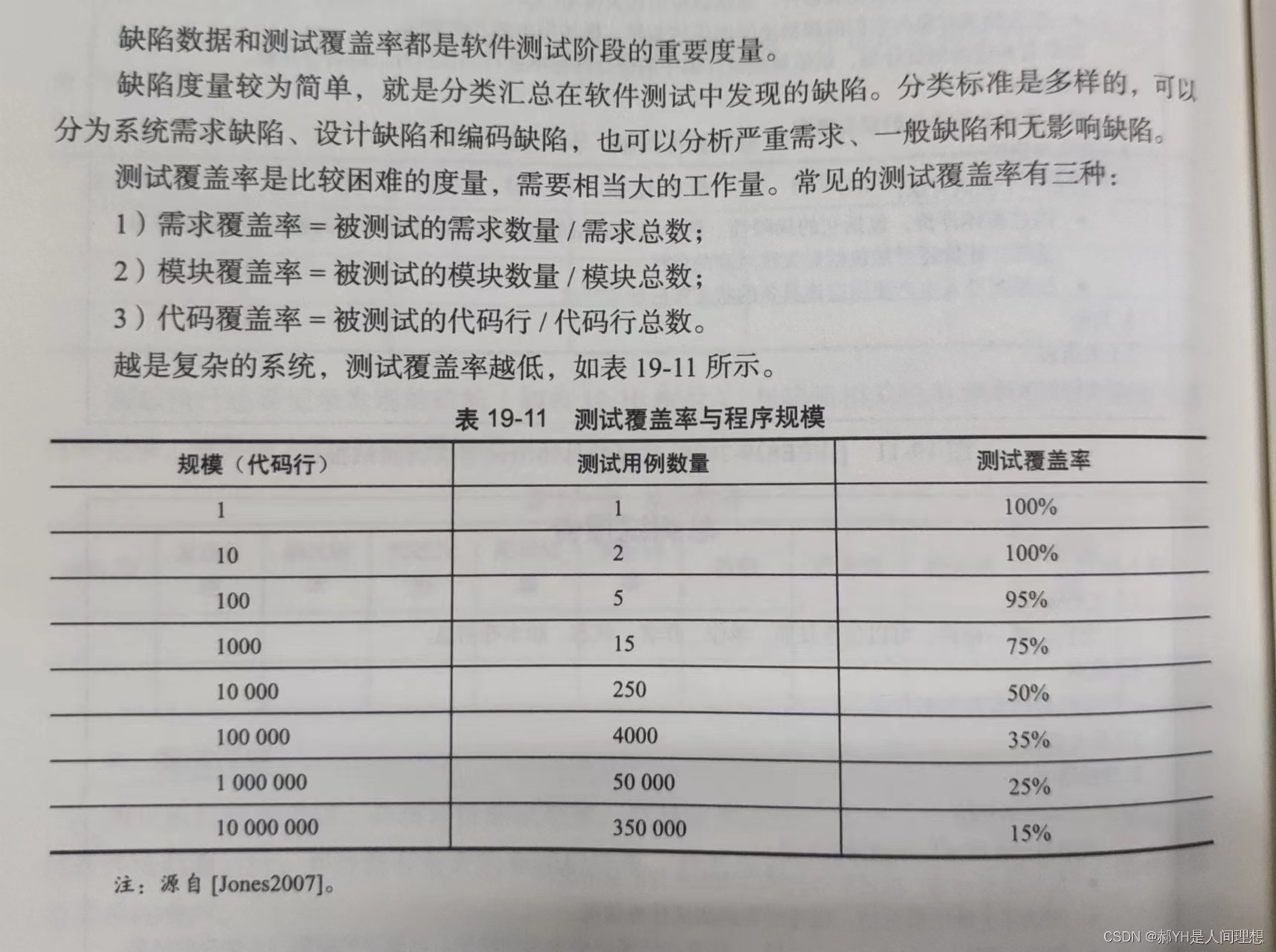
软件工程与计算总结(十九)软件测试
目录 编辑 一.引言 1.验证与确认 2.目标 3.测试用例 4.桩与驱动 5.缺陷、错误与失败 二.测试层次 1.测试层次的划分 2.单元测试 3.集成测试 4.系统测试 三.测试技术 1.测试用例的选择 2.随机测试 3.基于规格的技术(黑盒测试) 4.基于代…...

Tomcat设置IP黑名单和白名单server.xml
方式一: -- 只允许192.168.1.2和192.168.2.3 <Context path"" docBase"xxxAdmin" debug"0" reloadable"true" ><Valve className"org.apache.catalina.valves.RemoteAddrValve" allow"192.168.1.…...

【AI视野·今日NLP 自然语言处理论文速览 第五十五期】Mon, 16 Oct 2023
AI视野今日CS.NLP 自然语言处理论文速览 Mon, 16 Oct 2023 Totally 53 papers 👉上期速览✈更多精彩请移步主页 Daily Computation and Language Papers PromptRE: Weakly-Supervised Document-Level Relation Extraction via Prompting-Based Data Programming Au…...

k8s crd设置额外header
可以通过设置crd.spec.additionalPrinterColumns来实现: apiVersion: apiextensions.k8s.io/v1 kind: CustomResourceDefinition metadata:name: crontabs.stable.example.com spec:group: stable.example.comscope: Namespacednames:plural: crontabssingular: cr…...

电容笔好还是触屏笔好?便宜又好用的电容笔推荐
目前有哪些电容笔值得买?相比于之前的电容笔,现在的电容笔增加了很多新的特性功能,例如防误触、避免手指不小心触碰屏幕造成书写错误、笔画粗细可以自由调整等。苹果最初的Pencil现在售价一直高居不下。所以,如果你没有过多的预算…...

列表作为条件查询的参数
<if test"secucodeList ! null and secucodeList.size() > 0">...
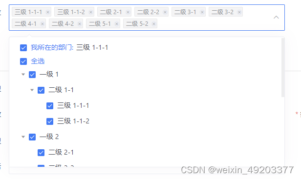
elementui中el-select和el-tree实现下拉树形多选功能
实现效果如下: 代码如下: html中 <el-col :lg"12"><el-form-item label"可用单位" prop"useOrgListTemp"><div class"departAll"><el-selectref"selectTree"v-model"valu…...

手机怎么监控电脑?
随着企业对电脑监控需求的增加,越来越多的管理者意识到使用电脑监控电脑的不便性,一旦外出就无法实时查看监控。其实可以用手机实现监控电脑的需求,只需在被监控端安装电脑监控软件后,将电脑设备和员工信息进行绑定,使…...
)
职场题:有一件特别紧急的事,群众要办理,且联系不上领导,你怎么办?(2)
接1所写 如果无法联系上领导且有一项特别紧急的事情需要办理,以下是进一步的建议: 11. 尝试其他沟通渠道:除了直接联系领导外,尝试通过其他沟通渠道与领导取得联系。这可能包括电子邮件、即时通讯工具或其他内部通信平台。确保详…...
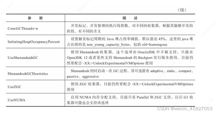
《深入理解java虚拟机 第三版》学习笔记一
第 2 章 Java 内存区域与内存溢出异常 2.2 运行时数据区域 Java 虚拟机在执行 Java 程序的过程中会把它所管理的内存划分为若干个不同的数据区域。这些区域有各自的用途,以及创建和销毁的时间,有的区域随着虚拟机进程的启动而一直存在,有些…...

webGL编程指南 第三章 旋转三角形
我会持续更新关于wegl的编程指南中的代码。 当前的代码不会使用书中的缩写,每一步都是会展开写。希望能给后来学习的一些帮助 git代码地址 接着 上一节 接着做平移的转化。本案例是三角形的旋转 <!DOCTYPE html> <html lang"en"><head…...

网络安全是什么?一文认识网络安全
一、网络安全 1.概念 网络安全从其本质上讲就是网络上的信息安全,指网络系统的硬件、软件及数据受到保护。不遭受破坏、更改、泄露,系统可靠正常地运行,网络服务不中断。 (1)基本特征 网络安全根据其本质的界定&#…...

LeetCode 2897. 对数组执行操作使平方和最大【贪心,位运算,哈希表】2301
本文属于「征服LeetCode」系列文章之一,这一系列正式开始于2021/08/12。由于LeetCode上部分题目有锁,本系列将至少持续到刷完所有无锁题之日为止;由于LeetCode还在不断地创建新题,本系列的终止日期可能是永远。在这一系列刷题文章…...

linux加密安全和时间同步
sudo实现授权 添加 vim /etc/sudoers luo ALL(root) /usr/bin/mount /deb/cdrom /mnt/ test ALL(root:ALL) ALL 在所有主机上 提权为root用户, 可以执行所有命令 户"test"被授权以"root"用户身份在任意主机上执行任意命令 切换luo用户使用 su…...

在Go中处理异常
引言 程序遇到的错误大致分为两类:程序员预料到的错误和程序员没有预料到的错误。我们在前两篇关于[错误处理]的文章中介绍的error接口主要处理我们在编写Go程序时预期的错误。error接口甚至允许我们承认函数调用发生错误的罕见可能性,因此我们可以在这些情况下进行…...

rust 全局变量
文章目录 编译期初始化静态常量静态变量原子类型 运行期初始化lazy_staticBox::leak从函数中返回全局变量 标准库中的 OnceCell 编译期初始化 静态常量 const MAX_ID: usize usize::MAX / 2; fn main() {println!("用户ID允许的最大值是{}",MAX_ID); }关键字是co…...

使用Python的qrcode库生成二维码
使用Python的qrcode库生成二维码 此二维码直接跳转对应的网址。 1、首先安装qrcode包 pip install qrcode2、运行代码 import qrcode# 需要跳转的URL url "https://blog.csdn.net/weixin_45092662?typeblog" img qrcode.make(url) img.save("qrcode.png&…...
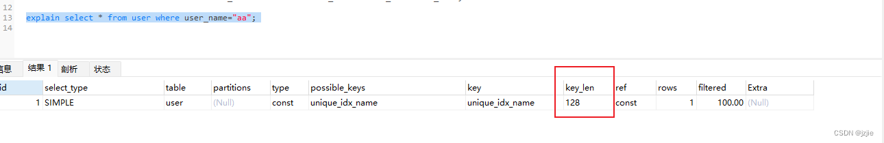
MSQL系列(四) Mysql实战-索引分析Explain命令详解
Mysql实战-索引分析Explain命令详解 前面我们讲解了索引的存储结构,我们知道了BTree的索引结构,也了解了索引最左侧匹配原则,到底最左侧匹配原则在我们的项目中有什么用?或者说有什么影响?今天我们来实战操作一下&…...

【微信小程序更新机制全解析】原理、实践与最佳实践
前言 微信小程序的更新机制,是连接开发者版本迭代与用户体验的核心桥梁。它设计的核心逻辑是**“自动无感更新为主,手动强制更新为辅”,在保证小程序快速启动、稳定可用**的前提下,尽可能让用户使用最新版本;同时为开…...

从Async到Sync,从SDR到DDR:一次NAND Flash接口升级引发的“血案”与调试实录
从Async到Sync,从SDR到DDR:一次NAND Flash接口升级引发的“血案”与调试实录 那天下午,当示波器上扭曲的DQS信号波形终于变得规整时,我瘫坐在工位上,手里的咖啡早已凉透。这次NAND Flash接口升级引发的连锁反应&#…...
)
《QGIS快速入门与应用基础》253:元素锁定(防止误操作)
作者:翰墨之道,毕业于国际知名大学空间信息与计算机专业,获硕士学位,现任国内时空智能领域资深专家、CSDN知名技术博主。多年来深耕地理信息与时空智能核心技术研发,精通 QGIS、GrassGIS、OSG、OsgEarth、UE、Cesium、OpenLayers、Leaflet、MapBox 等主流工具与框架,兼具…...

用Multisim复刻经典24秒篮球计时器:从555时钟到数码管显示的保姆级仿真教程
用Multisim复刻经典24秒篮球计时器:从555时钟到数码管显示的保姆级仿真教程 篮球比赛中那令人窒息的最后24秒倒计时,不仅是球员的决胜时刻,也是电子爱好者眼中完美的数字电路实践案例。本文将带你用Multisim从零搭建一个完整的24秒计时系统&a…...

【Java等保三级最小可行合规方案】:从Spring Boot 2.7到3.2,仅需修改8处配置+3个注解
第一章:Java等保三级合规的底层逻辑与演进脉络等保三级(GB/T 22239-2019《信息安全技术 网络安全等级保护基本要求》)对Java应用系统提出了覆盖“安全物理环境、安全通信网络、安全区域边界、安全计算环境、安全管理中心”五大层面的强制性约…...

N_m3u8DL-RE:突破流媒体下载限制的全场景解决方案 - 开发者与内容创作者的高效工具
N_m3u8DL-RE:突破流媒体下载限制的全场景解决方案 - 开发者与内容创作者的高效工具 【免费下载链接】N_m3u8DL-RE Cross-Platform, modern and powerful stream downloader for MPD/M3U8/ISM. English/简体中文/繁體中文. 项目地址: https://gitcode.com/GitHub_…...

C++学习笔记——初始化列表、创建和实例化对象、new 关键字、隐式构造与 explicit 关键字、运算符与运算符重载
目录 1. 初始化列表 1.1 基本语法 1.2 为什么使用初始化列表? 1.3 初始化顺序 2. 创建和实例化对象 2.1 栈上分配(自动存储期) 2.2 堆上分配(动态存储期) 2.3 栈 vs 堆:Cherno 的建议 3. new 关键…...

Qwen3-VL-30B效果实测:识别复杂图表毫无压力,回答精准又详细
Qwen3-VL-30B效果实测:识别复杂图表毫无压力,回答精准又详细 1. 开篇:当AI真正"看懂"了世界 想象一下这样的场景:你随手拍下一张满是数据和曲线的科研论文图表,AI不仅能准确识别出每个坐标轴的含义&#x…...
)
别再傻傻分不清了!手把手教你选对安规电容(X1/X2/Y1/Y2等级详解)
电子工程师必读:安规电容X/Y等级实战选型指南 当你在设计一款家用空气净化器的开关电源时,突然发现EMC测试总是不达标;当你维修一台工业变频器时,发现安规电容爆裂导致设备瘫痪——这些场景背后,往往隐藏着对X1/X2/Y1/…...
)
保姆级教程:用ArduPilot给无人车/船配置避障(附MR72雷达、TFmini Plus参数)
保姆级教程:用ArduPilot为无人车/船配置毫米波与激光雷达避障系统 当你的无人车在野外自动巡航时突然检测到前方障碍物,是紧急刹车还是智能绕行?水面无人船在夜间航行如何避开漂浮物?本文将手把手带你完成从硬件选型到参数调优的全…...