【STM32】RCC时钟模块(使用HAL库)
https://gitee.com/linhir-linhir/stm32-f103-c8/blob/master/STM32%E6%9C%80%E6%96%B0%E5%9B%BA%E4%BB%B6%E5%BA%93v3.5/Libraries/STM32F10x_StdPeriph_Driver/inc/stm32f10x_rcc.h
STM32最新固件库v3.5/Libraries/CMSIS/CM3/DeviceSupport/ST/STM32F10x/system_stm32f10x.c · 林何/STM32F103C8 - 码云 - 开源中国 (gitee.com)
1.宏定义
1.宏定义的位置
如果这个宏定义只能在.c文件中使用,则应该在.c文件中定义
如果这个宏定义既可以在.c或者.h文件中使用,则应该在.h中定义
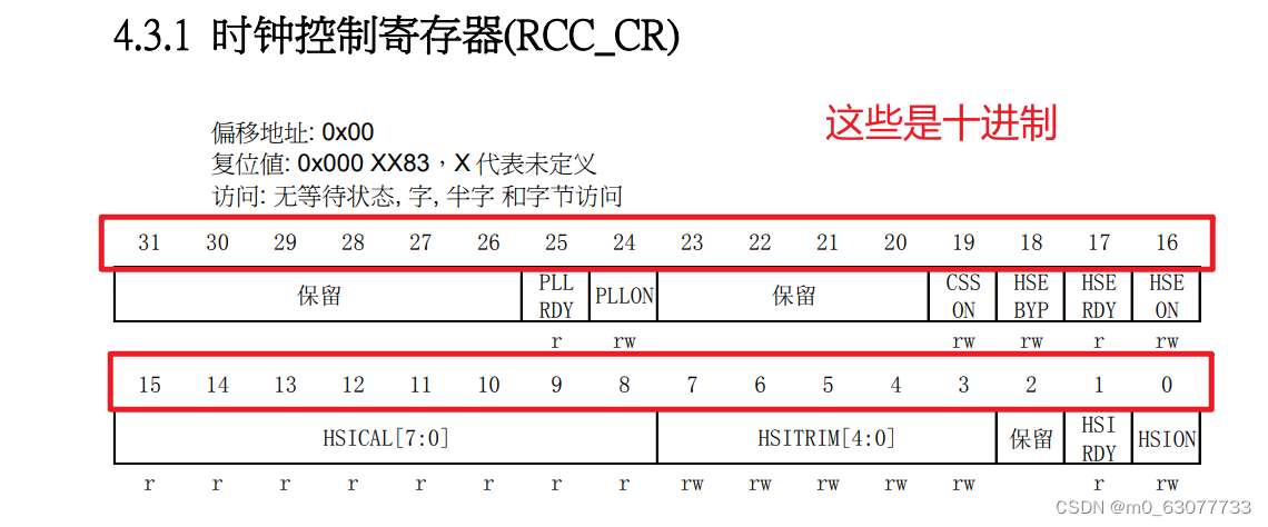
2.位带:RCC_OFFSET
因为我们STM32是32位的寄存器,所以如果我们只想要操作寄存器其中的一位,所以我们可以使用位移操作
/* ------------ RCC registers bit address in the alias region ----------- */
/*RCC_OFFSET:等价于RCC的基地址和外设寄存器之差
*/
/*!< PERIPH_BAS--》 Peripheral base address in the alias region */#define RCC_OFFSET                (RCC_BASE - PERIPH_BASE)
3.第一个寄存器:CR
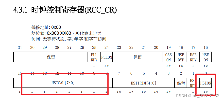
1.HSION
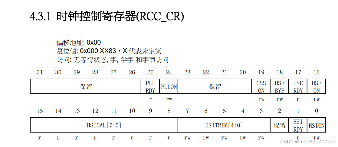
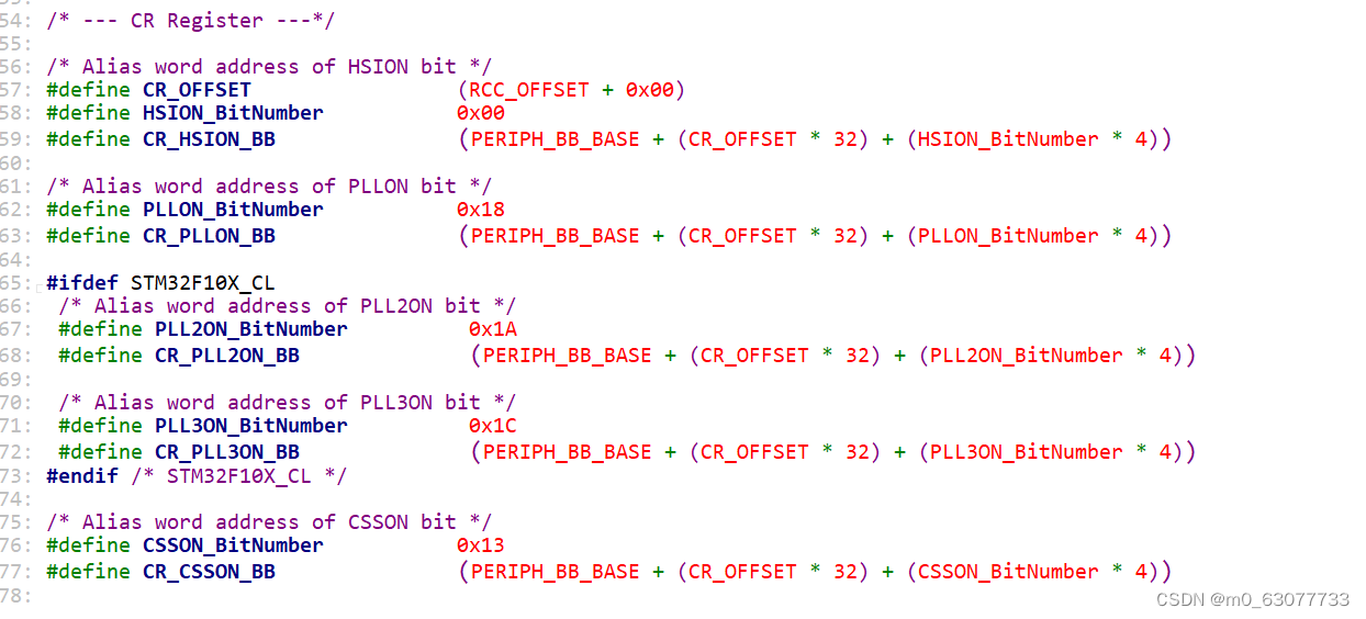
/* --- CR Register ---*//* Alias word address of HSION bit */
//这个寄存器相对于基地址的位置
#define CR_OFFSET (RCC_OFFSET + 0x00)
//操作HSION这一位相对于整个CR寄存器的偏移量
#define HSION_BitNumber 0x00
//CR寄存器中的HSION中的位带
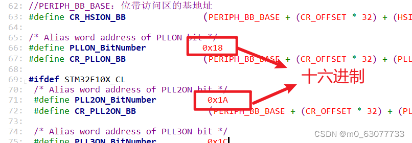
//PERIPH_BB_BASE:位带访问区的基地址
#define CR_HSION_BB (PERIPH_BB_BASE + (CR_OFFSET * 32) + (HSION_BitNumber * 4))
如果想要对其进行设置,就直接给CR_HSION_BB赋值
2.PLLON
/* Alias word address of PLLON bit */
#define PLLON_BitNumber           0x18
#define CR_PLLON_BB               (PERIPH_BB_BASE + (CR_OFFSET * 32) + (PLLON_BitNumber * 4))
4.RCC registers bit mask
Reset:进行位与置0
Set:进行位或置1
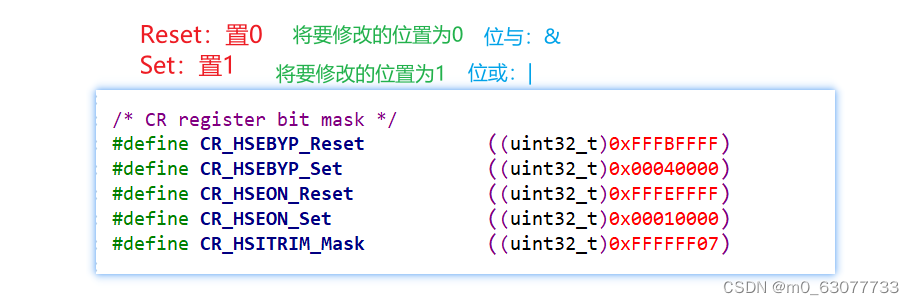
/* ---------------------- RCC registers bit mask ------------------------ *//* CR register bit mask */
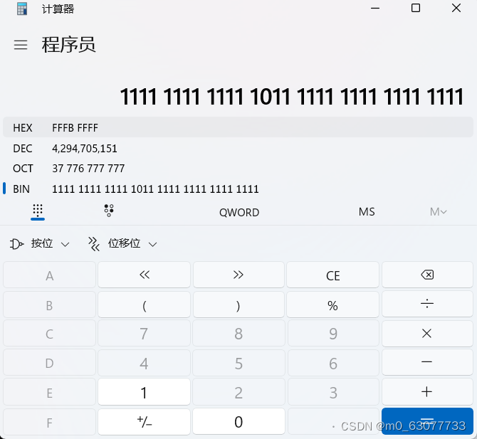
#define CR_HSEBYP_Reset ((uint32_t)0xFFFBFFFF)
#define CR_HSEBYP_Set ((uint32_t)0x00040000)
#define CR_HSEON_Reset ((uint32_t)0xFFFEFFFF)
#define CR_HSEON_Set ((uint32_t)0x00010000)
#define CR_HSITRIM_Mask ((uint32_t)0xFFFFFF07)
2.全局变量
定义了预分配处理器
1.static
c语言中static关键字用法详解_static在c语言中的用法-CSDN博客
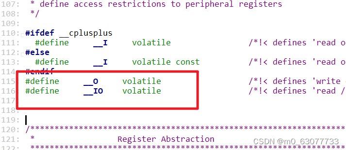
2.volatile
这个变量跟某一个寄存器的值进行绑定,寄存器里面有一个值是硬件可以改动的值
C语言丨深入理解volatile关键字-腾讯云开发者社区-腾讯云 (tencent.com)
3.uint
uint8:表示unsigned short
uint16:表示unsigned char
uint32:表示unsigned int
static __I uint8_t APBAHBPrescTable[16] = {0, 0, 0, 0, 1, 2, 3, 4, 1, 2, 3, 4, 6, 7, 8, 9};
static __I uint8_t ADCPrescTable[4] = {2, 4, 6, 8};
3.函数
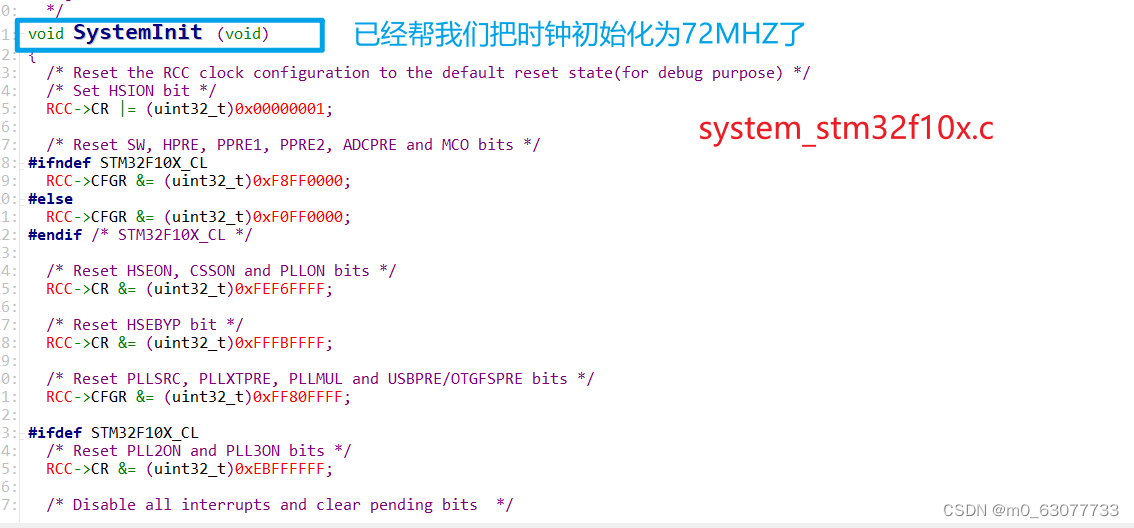
1.RCC_DeInit
/*** @brief  Resets the RCC clock configuration to the default reset state.* @param  None* @retval None*/
void RCC_DeInit(void)
{/* Set HSION bit */
//将CR这个位写为1RCC->CR |= (uint32_t)0x00000001;/* Reset SW, HPRE, PPRE1, PPRE2, ADCPRE and MCO bits */
#ifndef STM32F10X_CLRCC->CFGR &= (uint32_t)0xF8FF0000;
#else//非CL的芯片使用RCC->CFGR &= (uint32_t)0xF0FF0000;
#endif /* STM32F10X_CL */   /* Reset HSEON, CSSON and PLLON bits */
//HSEON, CSSON and PLLON:将这几位置0RCC->CR &= (uint32_t)0xFEF6FFFF;/* Reset HSEBYP bit */RCC->CR &= (uint32_t)0xFFFBFFFF;/* Reset PLLSRC, PLLXTPRE, PLLMUL and USBPRE/OTGFSPRE bits */RCC->CFGR &= (uint32_t)0xFF80FFFF;#ifdef STM32F10X_CL/* Reset PLL2ON and PLL3ON bits */RCC->CR &= (uint32_t)0xEBFFFFFF;/* Disable all interrupts and clear pending bits  */RCC->CIR = 0x00FF0000;/* Reset CFGR2 register */RCC->CFGR2 = 0x00000000;
#elif defined (STM32F10X_LD_VL) || defined (STM32F10X_MD_VL) || defined (STM32F10X_HD_VL)/* Disable all interrupts and clear pending bits  */RCC->CIR = 0x009F0000;/* Reset CFGR2 register */RCC->CFGR2 = 0x00000000;
#else/* Disable all interrupts and clear pending bits  */RCC->CIR = 0x009F0000;
#endif /* STM32F10X_CL */}
2.RCC_HSEConfig
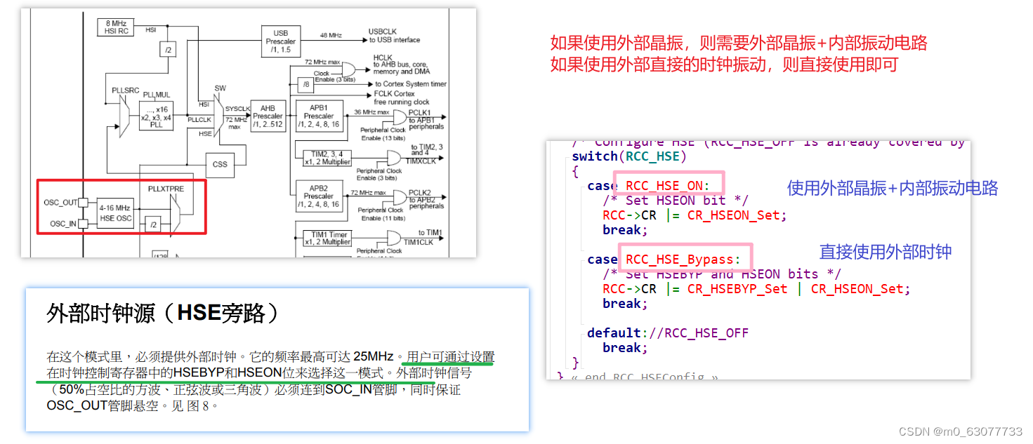
可以关闭时钟,所以平时我们不操纵它
这个HSEConfig实际效果:控制CPU是使用
外部晶振+内部振动电路 VS 外部时钟
1.assert:断言
assert机制是c语言用来判断一个东西是对的还是错的,如果是对的直接忽略过去,如果是错的就以某一种方式告诉我们(warrning error)让我们去修改。
/* Exported macro ------------------------------------------------------------*/
#ifdef  USE_FULL_ASSERT
/*** @brief  The assert_param macro is used for function's parameters check.* @param  expr: If expr is false, it calls assert_failed function which reports *         the name of the source file and the source line number of the call *         that failed. If expr is true, it returns no value.* @retval None*/#define assert_param(expr) ((expr) ? (void)0 : assert_failed((uint8_t *)__FILE__, __LINE__))
/* Exported functions ------------------------------------------------------- */void assert_failed(uint8_t* file, uint32_t line);
#else#define assert_param(expr) ((void)0)
#endif /* USE_FULL_ASSERT */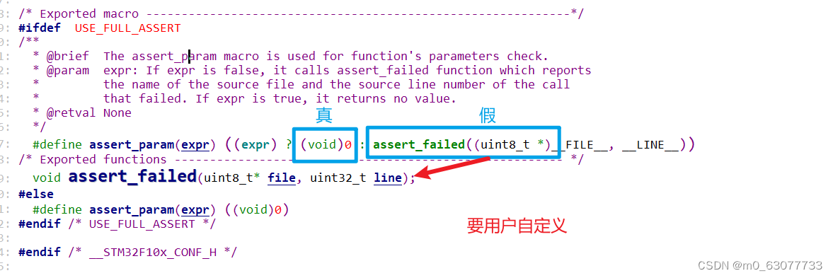
这个函数要用户自己去实现
void assert_failed(uint8_t* file, uint32_t line)
{ /* User can add his own implementation to report the file name and line number,ex: printf("Wrong parameters value: file %s on line %d\r\n", file, line) *//* Infinite loop *///用户用自己的方法去报错一个断言错误//用户可以用#error灯方法来在编译时报错(前提是断言表达式必须在预处理时就能有结果)//更常见的方式是用户在运行时报错,用printf打印调试信息//while (1){}
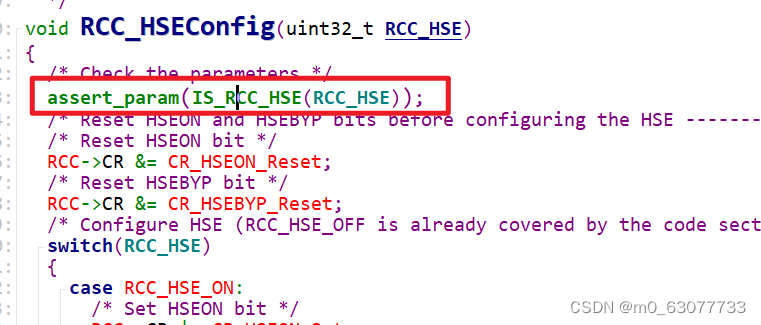
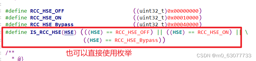
}2.判断用户输入的参数是否正确
3.代码理解
/*** @brief  Configures the External High Speed oscillator (HSE).* @note   HSE can not be stopped if it is used directly or through the PLL as system clock.* @param  RCC_HSE: specifies the new state of the HSE.*   This parameter can be one of the following values:*     @arg RCC_HSE_OFF: HSE oscillator OFF*     @arg RCC_HSE_ON: HSE oscillator ON*     @arg RCC_HSE_Bypass: HSE oscillator bypassed with external clock* @retval None*/
void RCC_HSEConfig(uint32_t RCC_HSE)
{/* Check the parameters */assert_param(IS_RCC_HSE(RCC_HSE));/* Reset HSEON and HSEBYP bits before configuring the HSE ------------------*//* Reset HSEON bit */RCC->CR &= CR_HSEON_Reset;/* Reset HSEBYP bit */RCC->CR &= CR_HSEBYP_Reset;/* Configure HSE (RCC_HSE_OFF is already covered by the code section above) */switch(RCC_HSE){case RCC_HSE_ON:/* Set HSEON bit */RCC->CR |= CR_HSEON_Set;break;case RCC_HSE_Bypass:/* Set HSEBYP and HSEON bits */RCC->CR |= CR_HSEBYP_Set | CR_HSEON_Set;break;default://RCC_HSE_OFFbreak;}
}
3.RCC_WaitForHSEStartUp(等待HSE)
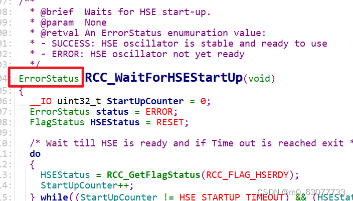
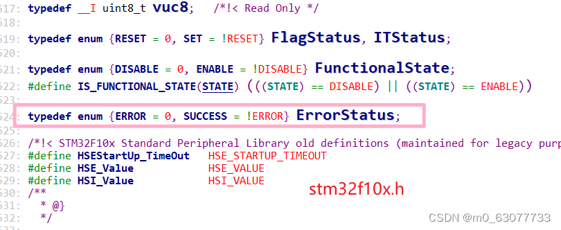
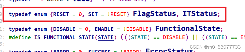
1.ErrorStatus
判断是否成功
一般:0:表示失败
1:表示成功
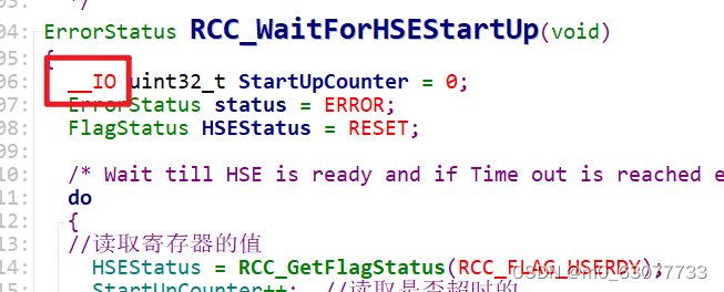
2.计数值加上volatile
因为这个变量是我们来进行判断是否超时的局部变量,所以每当我们调用这个函数的时候,应该将这个计数值清0,所以这里才使用
3.代码理解
/*** @brief Waits for HSE start-up.* @param None* @retval An ErrorStatus enumuration value:* - SUCCESS: HSE oscillator is stable and ready to use* - ERROR: HSE oscillator not yet ready*/
ErrorStatus RCC_WaitForHSEStartUp(void)
{__IO uint32_t StartUpCounter = 0;ErrorStatus status = ERROR;FlagStatus HSEStatus = RESET;/* Wait till HSE is ready and if Time out is reached exit */do{//读取寄存器的值HSEStatus = RCC_GetFlagStatus(RCC_FLAG_HSERDY);StartUpCounter++; //读取是否超时的} while((StartUpCounter != HSE_STARTUP_TIMEOUT) && (HSEStatus == RESET));//这里判断是防止超时if (RCC_GetFlagStatus(RCC_FLAG_HSERDY) != RESET){status = SUCCESS;}else{//超时status = ERROR;} return (status);
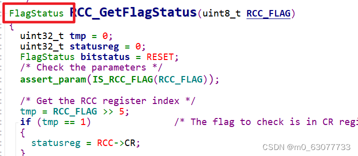
}4.RCC_GetFlagStatus(获取bit位状态)
1)确定这个RCC-FLAG在哪一个寄存器上
2)确定这个RCC_FLAG在寄存器是哪一个位上
1.返回值进行状态判断
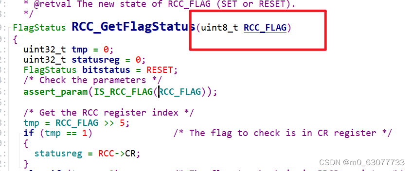
2.输入参数
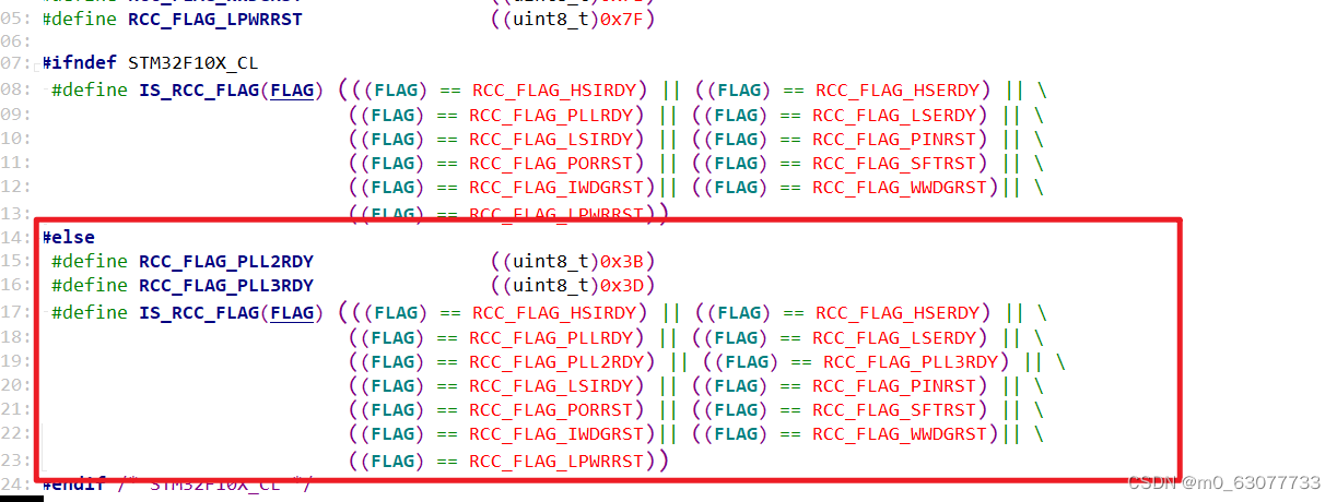
3.IS_RCC_FLAG
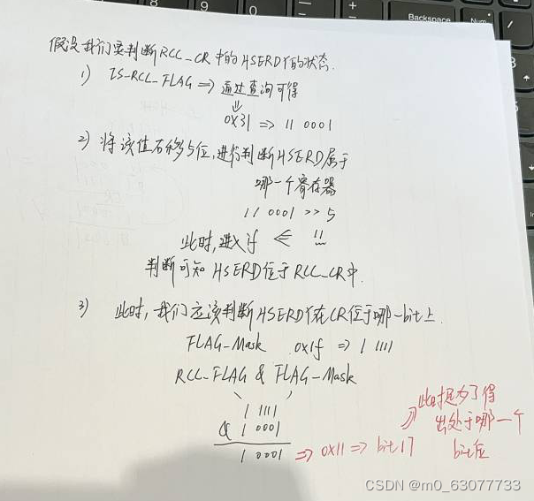
4.判断当前是在哪一个寄存器中
右移5位是想要判断第5位是1还是2还是3,然后进行判断是哪一个寄存器
/* Get the RCC register index *///将输入的标志位右移5位tmp = RCC_FLAG >> 5;//判断要访问哪一个寄存器if (tmp == 1) /* The flag to check is in CR register */{statusreg = RCC->CR;}else if (tmp == 2) /* The flag to check is in BDCR register */{statusreg = RCC->BDCR;}else /* The flag to check is in CSR register */{statusreg = RCC->CSR;}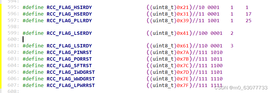
5.判断在寄存器的哪一个位上
/* Get the flag position *//**FLAG_Mask:0x1f*/tmp = RCC_FLAG & FLAG_Mask;if ((statusreg & ((uint32_t)1 << tmp)) != (uint32_t)RESET){bitstatus = SET;}else{bitstatus = RESET;}6.代码理解
/*** @brief  Checks whether the specified RCC flag is set or not.* @param  RCC_FLAG: specifies the flag to check.*   *   For @b STM32_Connectivity_line_devices, this parameter can be one of the*   following values:*     @arg RCC_FLAG_HSIRDY: HSI oscillator clock ready*     @arg RCC_FLAG_HSERDY: HSE oscillator clock ready*     @arg RCC_FLAG_PLLRDY: PLL clock ready*     @arg RCC_FLAG_PLL2RDY: PLL2 clock ready      *     @arg RCC_FLAG_PLL3RDY: PLL3 clock ready                           *     @arg RCC_FLAG_LSERDY: LSE oscillator clock ready*     @arg RCC_FLAG_LSIRDY: LSI oscillator clock ready*     @arg RCC_FLAG_PINRST: Pin reset*     @arg RCC_FLAG_PORRST: POR/PDR reset*     @arg RCC_FLAG_SFTRST: Software reset*     @arg RCC_FLAG_IWDGRST: Independent Watchdog reset*     @arg RCC_FLAG_WWDGRST: Window Watchdog reset*     @arg RCC_FLAG_LPWRRST: Low Power reset* *   For @b other_STM32_devices, this parameter can be one of the following values:        *     @arg RCC_FLAG_HSIRDY: HSI oscillator clock ready*     @arg RCC_FLAG_HSERDY: HSE oscillator clock ready*     @arg RCC_FLAG_PLLRDY: PLL clock ready*     @arg RCC_FLAG_LSERDY: LSE oscillator clock ready*     @arg RCC_FLAG_LSIRDY: LSI oscillator clock ready*     @arg RCC_FLAG_PINRST: Pin reset*     @arg RCC_FLAG_PORRST: POR/PDR reset*     @arg RCC_FLAG_SFTRST: Software reset*     @arg RCC_FLAG_IWDGRST: Independent Watchdog reset*     @arg RCC_FLAG_WWDGRST: Window Watchdog reset*     @arg RCC_FLAG_LPWRRST: Low Power reset*   * @retval The new state of RCC_FLAG (SET or RESET).*/
FlagStatus RCC_GetFlagStatus(uint8_t RCC_FLAG)
{uint32_t tmp = 0;uint32_t statusreg = 0;FlagStatus bitstatus = RESET;/* Check the parameters */assert_param(IS_RCC_FLAG(RCC_FLAG));/* Get the RCC register index *///将输入的标志位右移5位tmp = RCC_FLAG >> 5;//判断要访问哪一个寄存器if (tmp == 1)               /* The flag to check is in CR register */{statusreg = RCC->CR;}else if (tmp == 2)          /* The flag to check is in BDCR register */{statusreg = RCC->BDCR;}else                       /* The flag to check is in CSR register */{statusreg = RCC->CSR;}/* Get the flag position *//**FLAG_Mask:0x1f:1 1111*///这里我们可以得出应该将“1”移动几个bit//比如我们此时选中的RCC_FLAG=RCC->CR的HSERDY(此位对应bit17)//则此时tmp=11 0001    & 1 1111=1 0001(对应十进制17) tmp = RCC_FLAG & FLAG_Mask;//RESET表示置位:表示数值“0”if ((statusreg & ((uint32_t)1 << tmp)) != (uint32_t)RESET){//此时进入,表示该位已经被设置为1bitstatus = SET;}else{bitstatus = RESET;}/* Return the flag status */return bitstatus;
}
5.RCC_HSICmd(设置内部晶振状态)
发送命令的
/*** @brief  Enables or disables the Internal High Speed oscillator (HSI).* @note   HSI can not be stopped if it is used directly or through the PLL as system clock.* @param  NewState: new state of the HSI. This parameter can be: ENABLE or DISABLE.* @retval None*/
void RCC_HSICmd(FunctionalState NewState)
{/* Check the parameters */assert_param(IS_FUNCTIONAL_STATE(NewState));*(__IO uint32_t *) CR_HSION_BB = (uint32_t)NewState;
}
这里使用解引用的方式,因为我们这里只需要操纵一位
6.RCC_PLLConfig(设置时钟频率)
在使用这个PLL之前一定一定是没有使用PLL,才可以调用这个函数
配置PLL的时钟源倍频
1.参数:时钟倍频
2.参数:时钟PLL倍频系数
3.代码理解
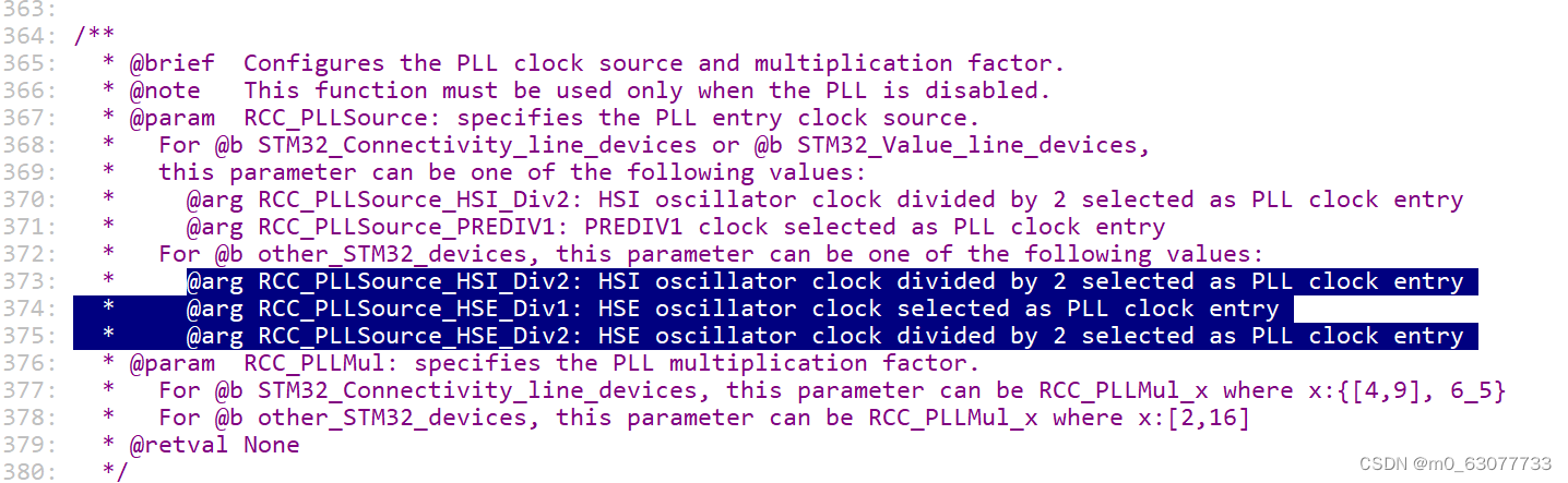
/*** @brief Configures the PLL clock source and multiplication factor.* @note This function must be used only when the PLL is disabled.* @param RCC_PLLSource: specifies the PLL entry clock source.* For @b STM32_Connectivity_line_devices or @b STM32_Value_line_devices, * this parameter can be one of the following values:* @arg RCC_PLLSource_HSI_Div2: HSI oscillator clock divided by 2 selected as PLL clock entry* @arg RCC_PLLSource_PREDIV1: PREDIV1 clock selected as PLL clock entry* For @b other_STM32_devices, this parameter can be one of the following values:* @arg RCC_PLLSource_HSI_Div2: HSI oscillator clock divided by 2 selected as PLL clock entry* @arg RCC_PLLSource_HSE_Div1: HSE oscillator clock selected as PLL clock entry* @arg RCC_PLLSource_HSE_Div2: HSE oscillator clock divided by 2 selected as PLL clock entry * @param RCC_PLLMul: specifies the PLL multiplication factor.* For @b STM32_Connectivity_line_devices, this parameter can be RCC_PLLMul_x where x:{[4,9], 6_5}* For @b other_STM32_devices, this parameter can be RCC_PLLMul_x where x:[2,16] * @retval None*/
void RCC_PLLConfig(uint32_t RCC_PLLSource, uint32_t RCC_PLLMul)
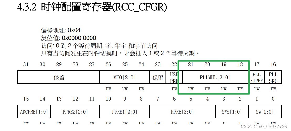
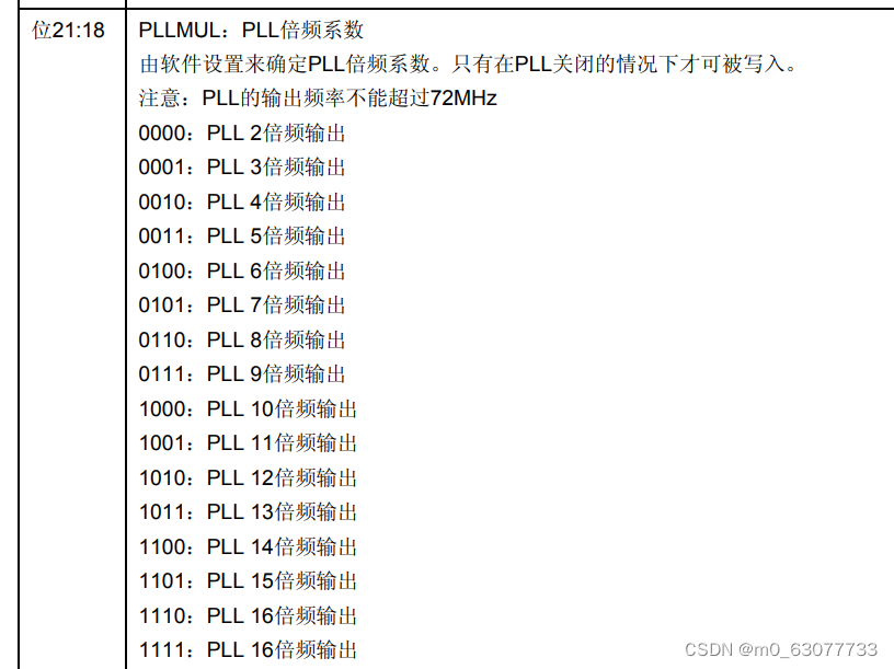
{uint32_t tmpreg = 0;/* Check the parameters */assert_param(IS_RCC_PLL_SOURCE(RCC_PLLSource));assert_param(IS_RCC_PLL_MUL(RCC_PLLMul));tmpreg = RCC->CFGR;//我们要操纵的2个参数都在CFGR/* Clear PLLSRC, PLLXTPRE and PLLMUL[3:0] bits */tmpreg &= CFGR_PLL_Mask;//清零/* Set the PLL configuration bits */tmpreg |= RCC_PLLSource | RCC_PLLMul;//置1/* Store the new value */RCC->CFGR = tmpreg;
}7.RCC_PREDIV1Config(与F1无关,此处不看)
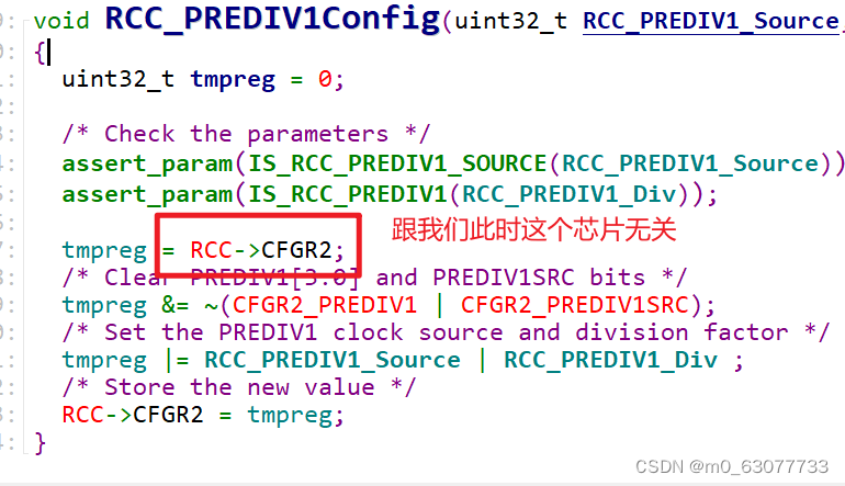
7.RCC_AHBPeriphClockCmd(外设时钟复位)
外设复位
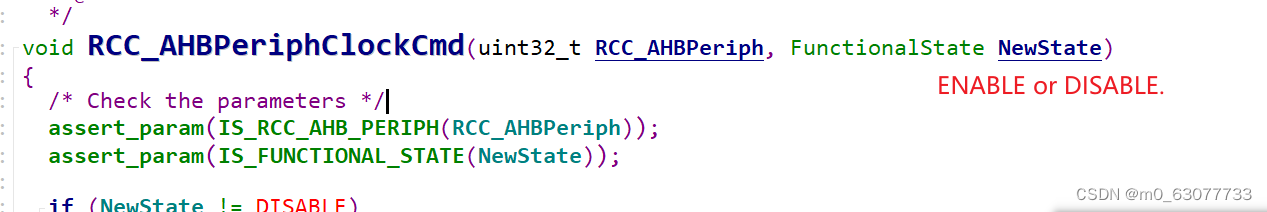
/*** @brief  Enables or disables the AHB peripheral clock.* @param  RCC_AHBPeriph: specifies the AHB peripheral to gates its clock.*   *   For @b STM32_Connectivity_line_devices, this parameter can be any combination*   of the following values:        *     @arg RCC_AHBPeriph_DMA1*     @arg RCC_AHBPeriph_DMA2*     @arg RCC_AHBPeriph_SRAM*     @arg RCC_AHBPeriph_FLITF*     @arg RCC_AHBPeriph_CRC*     @arg RCC_AHBPeriph_OTG_FS    *     @arg RCC_AHBPeriph_ETH_MAC   *     @arg RCC_AHBPeriph_ETH_MAC_Tx*     @arg RCC_AHBPeriph_ETH_MAC_Rx* *   For @b other_STM32_devices, this parameter can be any combination of the *   following values:        *     @arg RCC_AHBPeriph_DMA1*     @arg RCC_AHBPeriph_DMA2*     @arg RCC_AHBPeriph_SRAM*     @arg RCC_AHBPeriph_FLITF*     @arg RCC_AHBPeriph_CRC*     @arg RCC_AHBPeriph_FSMC*     @arg RCC_AHBPeriph_SDIO*   * @note SRAM and FLITF clock can be disabled only during sleep mode.* @param  NewState: new state of the specified peripheral clock.*   This parameter can be: ENABLE or DISABLE.* @retval None*/
void RCC_AHBPeriphClockCmd(uint32_t RCC_AHBPeriph, FunctionalState NewState)
{/* Check the parameters */assert_param(IS_RCC_AHB_PERIPH(RCC_AHBPeriph));assert_param(IS_FUNCTIONAL_STATE(NewState));if (NewState != DISABLE){RCC->AHBENR |= RCC_AHBPeriph;}else{RCC->AHBENR &= ~RCC_AHBPeriph;}
}
8.RCC_HCLKConfig(AHB频率)
配置AHB clock
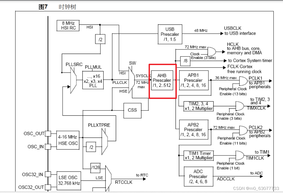
/*** @brief Configures the AHB clock (HCLK).* @param RCC_SYSCLK: defines the AHB clock divider. This clock is derived from * the system clock (SYSCLK).* This parameter can be one of the following values:* @arg RCC_SYSCLK_Div1: AHB clock = SYSCLK* @arg RCC_SYSCLK_Div2: AHB clock = SYSCLK/2* @arg RCC_SYSCLK_Div4: AHB clock = SYSCLK/4* @arg RCC_SYSCLK_Div8: AHB clock = SYSCLK/8* @arg RCC_SYSCLK_Div16: AHB clock = SYSCLK/16* @arg RCC_SYSCLK_Div64: AHB clock = SYSCLK/64* @arg RCC_SYSCLK_Div128: AHB clock = SYSCLK/128* @arg RCC_SYSCLK_Div256: AHB clock = SYSCLK/256* @arg RCC_SYSCLK_Div512: AHB clock = SYSCLK/512* @retval None*/
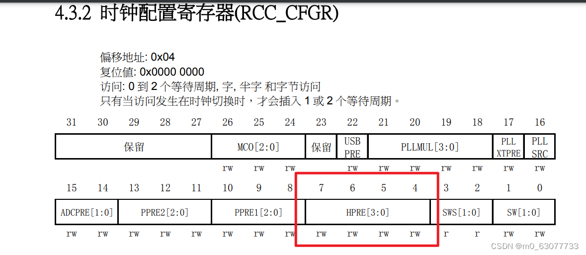
void RCC_HCLKConfig(uint32_t RCC_SYSCLK)
{uint32_t tmpreg = 0;/* Check the parameters *///判断要进行多少的分频assert_param(IS_RCC_HCLK(RCC_SYSCLK));//选择要进行操纵的寄存器tmpreg = RCC->CFGR;/* Clear HPRE[3:0] bits *//**CFGR_HPRE_Reset_Mask:0xFFFFFF0F==》0000 1111*///表示将CFGR的bit4-bit7位置0tmpreg &= CFGR_HPRE_Reset_Mask;/* Set HPRE[3:0] bits according to RCC_SYSCLK value *///表示将CFGR的bit4-bit7位置1tmpreg |= RCC_SYSCLK;/* Store the new value */RCC->CFGR = tmpreg;
}9.RCC_PCLK1Config(APB1频率)/RCC_PCLK2Config(APB2频率)
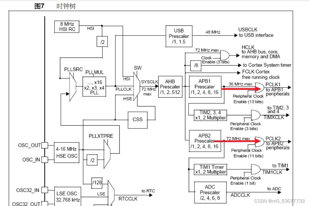
/*** @brief Configures the Low Speed APB clock (PCLK1).* @param RCC_HCLK: defines the APB1 clock divider. This clock is derived from * the AHB clock (HCLK).* This parameter can be one of the following values:* @arg RCC_HCLK_Div1: APB1 clock = HCLK* @arg RCC_HCLK_Div2: APB1 clock = HCLK/2* @arg RCC_HCLK_Div4: APB1 clock = HCLK/4* @arg RCC_HCLK_Div8: APB1 clock = HCLK/8* @arg RCC_HCLK_Div16: APB1 clock = HCLK/16* @retval None*/
void RCC_PCLK1Config(uint32_t RCC_HCLK)
{uint32_t tmpreg = 0;/* Check the parameters */assert_param(IS_RCC_PCLK(RCC_HCLK));tmpreg = RCC->CFGR;/* Clear PPRE1[2:0] bits */tmpreg &= CFGR_PPRE1_Reset_Mask;/* Set PPRE1[2:0] bits according to RCC_HCLK value */tmpreg |= RCC_HCLK;/* Store the new value */RCC->CFGR = tmpreg;
}/*** @brief Configures the High Speed APB clock (PCLK2).* @param RCC_HCLK: defines the APB2 clock divider. This clock is derived from * the AHB clock (HCLK).* This parameter can be one of the following values:* @arg RCC_HCLK_Div1: APB2 clock = HCLK* @arg RCC_HCLK_Div2: APB2 clock = HCLK/2* @arg RCC_HCLK_Div4: APB2 clock = HCLK/4* @arg RCC_HCLK_Div8: APB2 clock = HCLK/8* @arg RCC_HCLK_Div16: APB2 clock = HCLK/16* @retval None*/
void RCC_PCLK2Config(uint32_t RCC_HCLK)
{uint32_t tmpreg = 0;/* Check the parameters */assert_param(IS_RCC_PCLK(RCC_HCLK));tmpreg = RCC->CFGR;/* Clear PPRE2[2:0] bits */tmpreg &= CFGR_PPRE2_Reset_Mask;/* Set PPRE2[2:0] bits according to RCC_HCLK value */tmpreg |= RCC_HCLK << 3;/* Store the new value */RCC->CFGR = tmpreg;
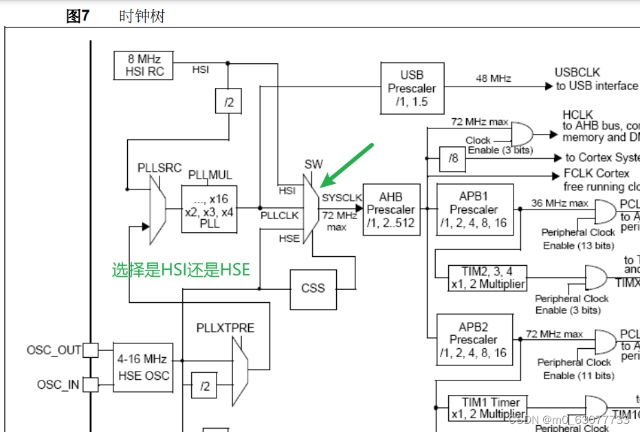
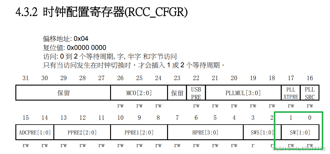
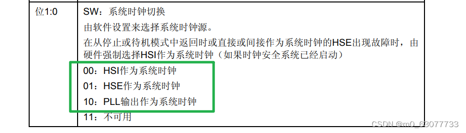
}10.RCC_SYSCLKConfig(选择使用哪一个作为系统时钟HSI/HSE/SYS)
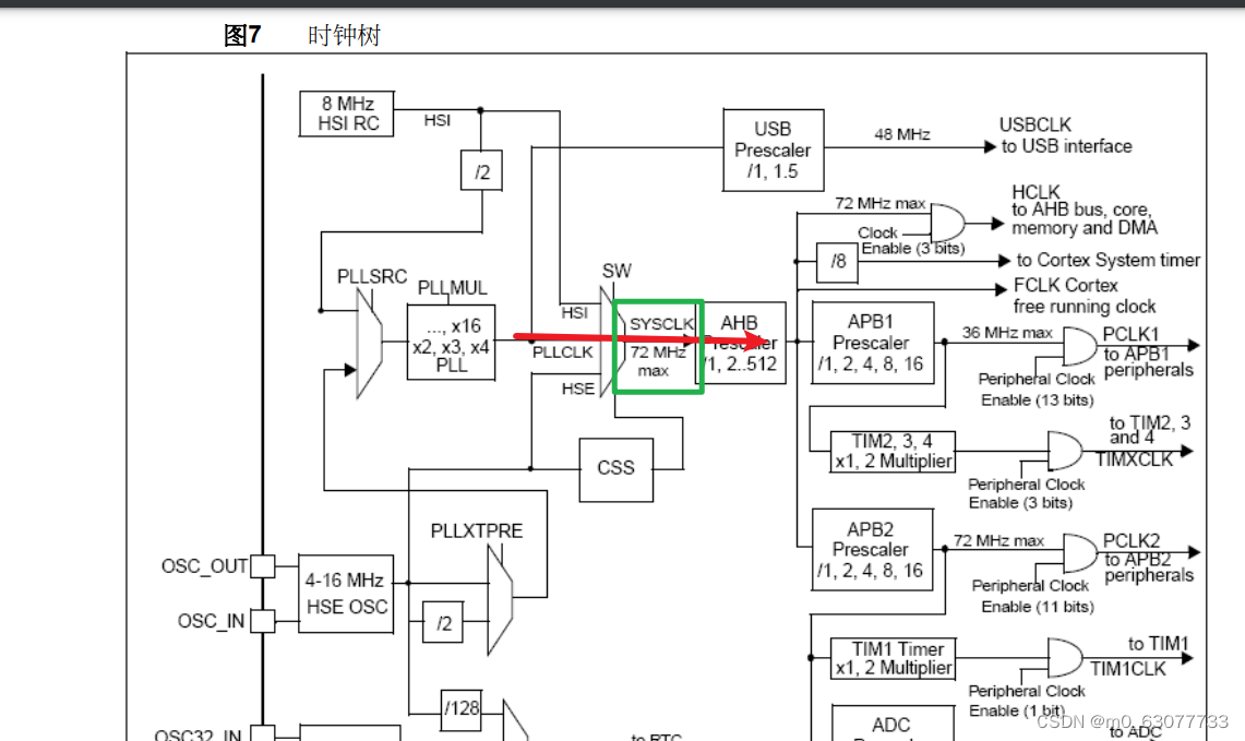
/*** @brief  Configures the system clock (SYSCLK).* @param  RCC_SYSCLKSource: specifies the clock source used as system clock.*   This parameter can be one of the following values:*     @arg RCC_SYSCLKSource_HSI: HSI selected as system clock*     @arg RCC_SYSCLKSource_HSE: HSE selected as system clock*     @arg RCC_SYSCLKSource_PLLCLK: PLL selected as system clock* @retval None*/
void RCC_SYSCLKConfig(uint32_t RCC_SYSCLKSource)
{uint32_t tmpreg = 0;/* Check the parameters *///判断用户输入的参数是否正确assert_param(IS_RCC_SYSCLK_SOURCE(RCC_SYSCLKSource));tmpreg = RCC->CFGR;/* Clear SW[1:0] bits */tmpreg &= CFGR_SW_Mask;//置0/* Set SW[1:0] bits according to RCC_SYSCLKSource value */tmpreg |= RCC_SYSCLKSource;//置1/* Store the new value */RCC->CFGR = tmpreg;
}
11.RCC_APB2PeriphResetCmd(外设的重新复位)
/*** @brief  Forces or releases High Speed APB (APB2) peripheral reset.* @param  RCC_APB2Periph: specifies the APB2 peripheral to reset.*   This parameter can be any combination of the following values:*     @arg RCC_APB2Periph_AFIO, RCC_APB2Periph_GPIOA, RCC_APB2Periph_GPIOB,*          RCC_APB2Periph_GPIOC, RCC_APB2Periph_GPIOD, RCC_APB2Periph_GPIOE,*          RCC_APB2Periph_GPIOF, RCC_APB2Periph_GPIOG, RCC_APB2Periph_ADC1,*          RCC_APB2Periph_ADC2, RCC_APB2Periph_TIM1, RCC_APB2Periph_SPI1,*          RCC_APB2Periph_TIM8, RCC_APB2Periph_USART1, RCC_APB2Periph_ADC3,*          RCC_APB2Periph_TIM15, RCC_APB2Periph_TIM16, RCC_APB2Periph_TIM17,*          RCC_APB2Periph_TIM9, RCC_APB2Periph_TIM10, RCC_APB2Periph_TIM11  * @param  NewState: new state of the specified peripheral reset.*   This parameter can be: ENABLE or DISABLE.* @retval None*/
void RCC_APB2PeriphResetCmd(uint32_t RCC_APB2Periph, FunctionalState NewState)
{/* Check the parameters */assert_param(IS_RCC_APB2_PERIPH(RCC_APB2Periph));assert_param(IS_FUNCTIONAL_STATE(NewState));if (NewState != DISABLE){RCC->APB2RSTR |= RCC_APB2Periph;}else{RCC->APB2RSTR &= ~RCC_APB2Periph;}
}
4.注意点:
1.进制问题
我们在寄存器中的偏移量都是以十进制进行设置的,如果想要将其定义在宏定义中,记得将其转换为十六进制
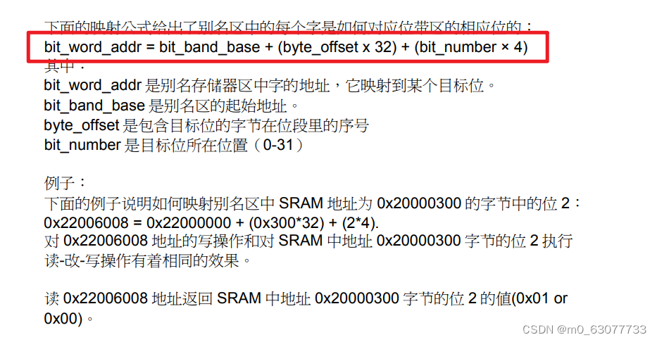
2.位段计算
5.使用库重写时钟设置函数
1.原始函数
#include "clock.h"
#include "gpio.h"void Set_SysClockTo72M(void){//检测外部晶振是否准备好unsigned int Rcc_CR_HSE_Ready=0;//等待开启PLL开启成功unsigned int Rcc_CR_PLL_Ready=0;//判断切换成PLL是否成功unsigned int RCC_CF_SWS_PLL=0;unsigned int faultTime=0;//判断等待是否超时//一、复位RCC_CR寄存器rRCC_CR = 0x00000083;//二、开启外部时钟(外部晶振)//第一步:先置0【将bit16清零】rRCC_CR &= ~(1<<16);//关闭HSEON//第二步:在置1rRCC_CR |= (1<<16);//打开HSEON,让HSE开始工作//三、检测外部时钟开启是否成功do{//检测HSEREAY(bit17)是否为1,1表示准备好Rcc_CR_HSE_Ready=rRCC_CR&(1<<17);//取出bit17faultTime++;}while((faultTime<0x0fffffff) && (Rcc_CR_HSE_Ready==0));//跳出do-while 1)要么超时2)要么准好了//判断是超时还是准备好//注意点:不能直接使用“Rcc_CR_HSE_Ready”因为rRCC_CR是需要读一次寄存器//但是读出的结果可能还未改变,所以一定不能直接使用if((rRCC_CR&(1<<17))!=0)//rRCC_CR&(1<<17)==1{//这里HSE就ready,下面再去配置PLL并且等待他ready//设置FlashrFLASH_ACR |= 0x10;rFLASH_ACR &= (~0x03);rFLASH_ACR |= (0x02);//四、对其进行预分频//HPRE【AHB】:对应bit4-bit7:不分频(000)//PPRE1【APB1】:对应bit8-bit10:进行二分频(100)//PPRE2【APB2】:对应bit11-bit13:不分频(000)//AHB和APB2未分频,APB1被2分频//所以最终:AHB和APB2都是72MHZ,APB1是36MHZ//第一步:先置0rRCC_CFGR &=(~((0x0f<<4) | (0x07<<8) | (0x07<<11)));//等价于:rRCC_CFGR=(~(0x3ff<<4));//第二步:置1rRCC_CFGR |=((0x0<<4) | (0x04<<8) | (0x0<<11));//五、设置SHE为输入时钟,同时HSE不分频//选择HSE作为PLL输入并且HSE不分频//设置为输入时钟:bit16//设置为不分频:bit17//第一步:先置0rRCC_CFGR &=(~((1<<16) | (1<<17)));//第二步:置1,bit16rRCC_CFGR |= ((1<<16) | (0<<17));//六、设置PLL倍频系数//9分频:0111:0x07rRCC_CFGR &=(~(0x0f<<18));//清零bit18-bit21rRCC_CFGR |= (0x07<<18);//设置为9倍频//七、打开PLL开关rRCC_CR |= (1<<24);//八、等待开启PLL开启成功//因为前面已经使用到,被累加了,使用这里要重新置0faultTime=0;do{led_init();Rcc_CR_PLL_Ready=rRCC_CR & (1<<25);//检测第25位是否为1faultTime++;}while((faultTime<0x0fffffff) && (Rcc_CR_PLL_Ready==0));if((rRCC_CR & (1<<25)) == (1<<25)){//到这里说明PLL已经稳定,可以用了,下面可以切换成外部时钟了//九、切换成PLLrRCC_CFGR &=(~(0x03)<<0);rRCC_CFGR |=(0x02<<0);//十、判断切换成PLL是否成功//因为前面已经使用到,被累加了,使用这里要重新置0faultTime=0;do{RCC_CF_SWS_PLL=rRCC_CFGR & (0x03<<2);//读出bit2-bit3faultTime++;led_init();//0x02<<2:表示此时转换成PLL}while ((faultTime<0x0FFFFFFF) && (RCC_CF_SWS_PLL!=(0x02<<2)));//十一、此时PLL转换成功if((rRCC_CFGR & (0x03<<2))==(0x02<<2)){//到这里我们的时钟整个就设置好了,可以结束了}else{//到这里说明PLL输出作为PLL失败while(1);}}else{//到这里说明PLL启动时出错了,PLL不能稳定工作while(1);}}else{//超时,或者未准备好,此时HSE不可以使用while(1);}}
2.自己封装一个RCC_WaitForPLLStartUp
此处我们参考【RCC_WaitForHSEStartUp】这个函数来自己写
由源文件中没有定义【PLL_STARTUP_TIMEOUT】所以我们要自定义
#define PLL_STARTUP_TIMEOUT   ((uint16_t)0x0500000)//本函数作用:等待PLL倍频后输出稳定
//返回值:SUCCESS说明未超时,ERROR超时
ErrorStatus RCC_WaitForPLLStartUp(void)
{__IO uint32_t StartUpCounter = 0;ErrorStatus status = ERROR;FlagStatus PLLStatus = RESET;/* Wait till HSE is ready and if Time out is reached exit */do{//读取寄存器的值PLLStatus = RCC_GetFlagStatus(RCC_FLAG_PLLRDY);StartUpCounter++;  //读取是否超时的} while((StartUpCounter != PLL_STARTUP_TIMEOUT) && (PLLStatus == RESET));//这里判断是防止超时if (RCC_GetFlagStatus(RCC_FLAG_PLLRDY) != RESET){status = SUCCESS;}else{//超时status = ERROR;}  return (status);
}
3.完整使用库函数的clock
//这个函数里面包含了全部外设头文件
#include "stm32f10x.h"
//等价于
//#include"stm32f10x_conf.h"#define PLL_STARTUP_TIMEOUT   ((uint16_t)0x0500000)//本函数作用:等待PLL倍频后输出稳定
//返回值:SUCCESS说明未超时,ERROR超时
ErrorStatus RCC_WaitForPLLStartUp(void)
{__IO uint32_t StartUpCounter = 0;ErrorStatus status = ERROR;FlagStatus PLLStatus = RESET;/* Wait till HSE is ready and if Time out is reached exit */do{//读取寄存器的值PLLStatus = RCC_GetFlagStatus(RCC_FLAG_PLLRDY);StartUpCounter++;  //读取是否超时的} while((StartUpCounter != PLL_STARTUP_TIMEOUT) && (PLLStatus == RESET));//这里判断是防止超时if (RCC_GetFlagStatus(RCC_FLAG_PLLRDY) != RESET){status = SUCCESS;}else{//超时status = ERROR;}  return (status);
}void Set_SysClockTo72M(void){//接收判断回来的HSE是否已经稳定ErrorStatus sta=ERROR;//faultTime:用来判断是否超时unsigned int faultTime=0;unsigned int RCC_CF_SWS_PLL=0;//一、先关闭HSEON然后在打开HSEONRCC_HSEConfig(RCC_HSE_ON);/*rRCC_CR = 0x00000083;rRCC_CR &= ~(1<<16);//关闭HSEONrRCC_CR |= (1<<16);//打开HSEON,让HSE开始工作*///二、等到HSE稳定sta=RCC_WaitForHSEStartUp();/*do{//检测HSEREAY(bit17)是否为1,1表示准备好Rcc_CR_HSE_Ready=rRCC_CR&(1<<17);//取出bit17faultTime++;}while((faultTime<0x0fffffff) && (Rcc_CR_HSE_Ready==0));//跳出do-while 1)要么超时2)要么准好了*///三、判断是HSE稳定了还是超时了if(sta==SUCCESS)//if((rRCC_CR&(1<<17))!=0)//rRCC_CR&(1<<17)==1{//这里HSE就ready,下面再去配置PLL并且等待他ready//四、设置FlashFLASH->ACR |= 0x10;FLASH->ACR  &= (~0x03);FLASH->ACR  |= (0x02);/*rFLASH_ACR |= 0x10;rFLASH_ACR &= (~0x03);rFLASH_ACR |= (0x02);*///AHB和APB2未分频,APB1被2分频//所以最终:AHB和APB2都是72MHZ,APB1是36MHZ//五、配置相关的倍频信息//配置HCLK为SYSCLK/1RCC_HCLKConfig(RCC_SYSCLK_Div1);//配置PCLK1为JCLK的2分频RCC_PCLK1Config(RCC_HCLK_Div2);//配置PCLK2为JCLK的1分频RCC_PCLK2Config(RCC_HCLK_Div1);/*rRCC_CFGR &=(~((0x0f<<4) | (0x07<<8) | (0x07<<11)));//等价于:rRCC_CFGR=(~(0x3ff<<4));rRCC_CFGR |=((0x0<<4) | (0x04<<8) | (0x0<<11));*///六、设置HSE/1为PLL时钟源,PLL倍频系数为9RCC_PLLConfig(RCC_PLLSource_HSE_Div1,RCC_PLLMul_9);/*//设置SHE为输入时钟,同时HSE不分频rRCC_CFGR &=(~((1<<16) | (1<<17)));rRCC_CFGR |= ((1<<16) | (0<<17));//设置PLL倍频系数//9分频:0111:0x07rRCC_CFGR &=(~(0x0f<<18));//清零bit18-bit21rRCC_CFGR |= (0x07<<18);//设置为9倍频*///七、打开PLL开关RCC_PLLCmd(ENABLE);//rRCC_CR |= (1<<24);//因为HAL库中没有等到PLL的函数//此处我们参考【RCC_WaitForHSEStartUp】这个函数来自己写//八、等待开启PLL开启成功sta=RCC_WaitForPLLStartUp();/*//因为前面已经使用到,被累加了,使用这里要重新置0faultTime=0;do{led_init();Rcc_CR_PLL_Ready=rRCC_CR & (1<<25);//检测第25位是否为1faultTime++;}while((faultTime<0x0fffffff) && (Rcc_CR_PLL_Ready==0));*///九、判断PLL稳定还是超时//if((rRCC_CR & (1<<25)) == (1<<25)){if(sta==SUCCESS){//到这里说明PLL已经稳定,可以用了,下面可以切换成外部时钟了//九、切换成PLLRCC_SYSCLKConfig(RCC_SYSCLKSource_PLLCLK);/*rRCC_CFGR &=(~(0x03)<<0);rRCC_CFGR |=(0x02<<0);*/	//十、判断切换成PLL是否成功//因为前面已经使用到,被累加了,使用这里要重新置0faultTime=0;do{RCC_CF_SWS_PLL=RCC->CFGR & (0x03<<2);//读出bit2-bit3faultTime++;//0x02<<2:表示此时转换成PLL}while ((faultTime<0x0FFFFFFF) && (RCC_CF_SWS_PLL!=(0x02<<2)));//十一、此时PLL转换成功if((RCC->CFGR  & (0x03<<2))==(0x02<<2)){//到这里我们的时钟整个就设置好了,可以结束了}else{//到这里说明PLL输出作为PLL失败while(1);}}else{//到这里说明PLL启动时出错了,PLL不能稳定工作while(1);}}else{//超时,或者未准备好,此时HSE不可以使用while(1);}}
6.SystmInit注意点:
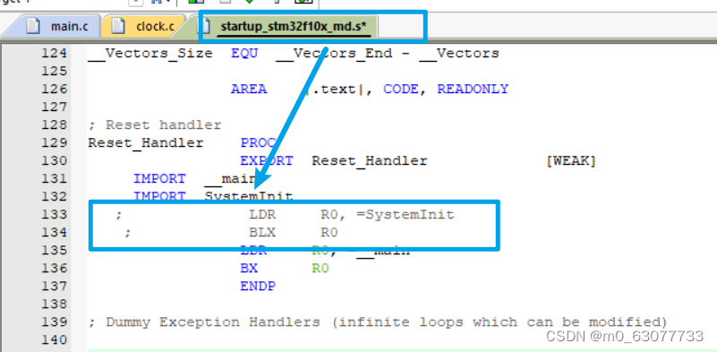
我们在“startup_stm32f10x_md.s”文件中可以看到在执行main函数之前会先执行一个“SystemInit”函数
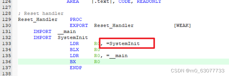
所以如果我们想要使用自己的设置72MHZ频率的函数,则应该将SystemInit注释调。
相关文章:
【STM32】RCC时钟模块(使用HAL库)
https://gitee.com/linhir-linhir/stm32-f103-c8/blob/master/STM32%E6%9C%80%E6%96%B0%E5%9B%BA%E4%BB%B6%E5%BA%93v3.5/Libraries/STM32F10x_StdPeriph_Driver/inc/stm32f10x_rcc.h STM32最新固件库v3.5/Libraries/CMSIS/CM3/DeviceSupport/ST/STM32F10x/system_stm32f10x.c…...

WPF中的绑定知识详解(含案例源码分享)
✅作者简介:2022年博客新星 第八。热爱国学的Java后端开发者,修心和技术同步精进。 🍎个人主页:Java Fans的博客 🍊个人信条:不迁怒,不贰过。小知识,大智慧。 💞当前专栏…...
【JVM】类的生命周期
【JVM】类的生命周期 文章目录 【JVM】类的生命周期1. 生命周期概述2. 加载阶段3. 连接阶段3.1 验证3.2 准备3.3 解析 4. 初始化阶段4.1 触发初始化的方式4.2 clinit不存在的情况4.3 多个类的初始化 5. 总结 1. 生命周期概述 类的生命周期分为5/7个阶段: 加载(Loa…...

asp.net网上商城系统VS开发sqlserver数据库web结构c#编程Microsoft Visual Studio协同过滤设计
一、源码特点 asp.net网上商城系统是一套完善的web设计管理系统系统采用协同过滤算法进行商品推荐,系统具有完整的源代码和数据库,系统主要采用B/S模式开发。开发环境为vs2010,数据库 为sqlserver2008,使用c#语言开发 ASP…...

APUS入驻百度灵境矩阵,普惠AI大模型插件能力
10月17日,APUS出席百度世界大会2023。会上,百度公布了灵境矩阵业务进展,APUS作为灵境矩阵首批合作伙伴正与百度携手拓展大模型能力边界、构建大模型应用生态。 百度认为,大模型将繁荣AI应用生态,在生态搭建过程中&…...

通过C++调用Com接口
头文件 #include <iostream> #include <Windows.h> #include <comdef.h> #include <rpcdce.h> using namespace std; #pragma comment(lib, "Rpcrt4.lib")72C24DD5-D70A-438B-8A42-98424B88AFB8 通过Wscript.Shell来创建进程: void Wscri…...
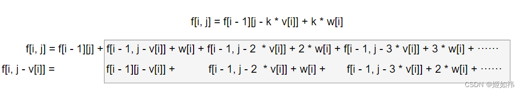
完全背包问题
目录 1. 朴素解法 2. 优化 原题链接: 3. 完全背包问题 - AcWing题库 题目描述: 有 N 种物品和一个容量是 V 的背包,每种物品都有无限件可用。 第 i 种物品的体积是 vi,价值是 wi。 求解将哪些物品装入背包,可使这些…...
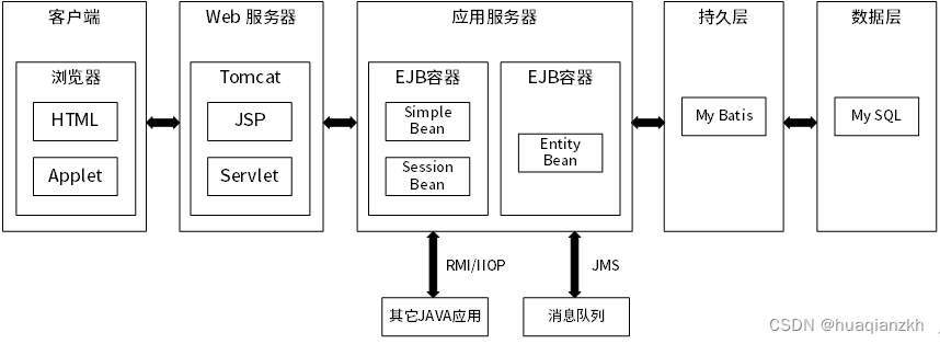
J2EE的N层体系结构
J2EE平台采用了多层分布式应用程序模型,实现不同逻辑功能的应用程序被封装到不同的构件中,处于不同层次的构件可被分别部署到不同的机器中。 RMI/IIOP:RMI(Remote Method Invocation,远程方法调用)是Java的…...

Quirks(怪癖)模式是什么?它和 Standards(标准)模式有什么区别?
目录 前言: 用法: 代码: Quirks模式示例: Standards模式示例: 理解: Quirks模式: Standards模式: 高质量讨论: 前言: "Quirks模式"和"Standards模式"是与HTML文档渲染模式相关的两种模式。它们影响着浏览器如何解释和渲染HT…...
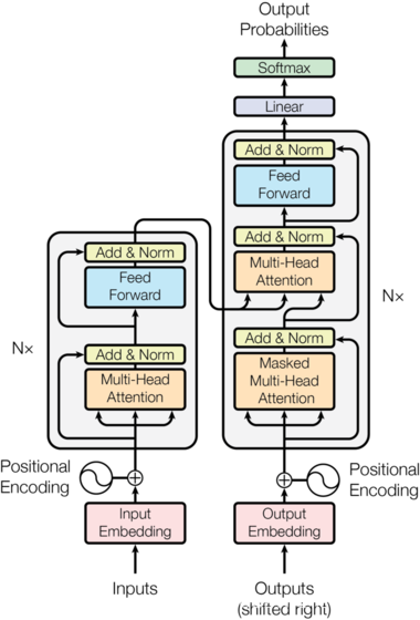
自然语言处理---Transformer模型
Transformer概述 相比LSTM和GRU模型,Transformer模型有两个显著的优势: Transformer能够利用分布式GPU进行并行训练,提升模型训练效率。 在分析预测更长的文本时,捕捉间隔较长的语义关联效果更好。 Transformer模型的作用 基于seq…...

动画系统的前世今生(一)
掐指一算,五年没更新过我的CSDN账号啦,方向也从人工智能变成了计算机图形学,当然也依旧会关注AI的发展,之前在知乎上写了一些文章[传送门],后续也会逐渐同步到CSDN上~ 这个系列将包含五篇文章,内…...

11 结构型模式- 代理模式
结构性模式一共包括七种: 代理模式、桥接模式、装饰者模式、适配器模式、门面(外观)模式、组合模式、和享元模式。 1 代理模式介绍 软件开发中的代理: 代理模式中引入了一个新的代理对象,代理对象在客户端对象和目标对象之间起到了中介的作用,它去掉客…...
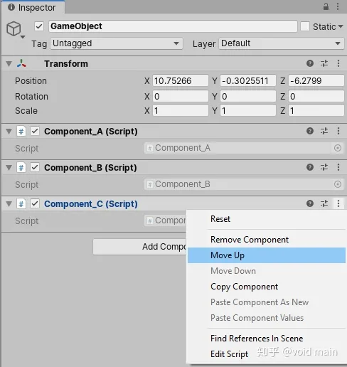
Unity--用户界面
目录 “使用工具栏”: “层次结构”窗口: 层次结构窗口 制作子GameObject “游戏”视图: “场景视图“: ”项目窗口“: 项目窗口工具栏: "Inspector" 窗口: Inspector 游戏…...

BUUCTF 乌镇峰会种图 1
BUUCTF:https://buuoj.cn/challenges 题目描述: 乌镇互联网大会召开了,各国巨头汇聚一堂,他们的照片里隐藏着什么信息呢?(答案格式:flag{答案},只需提交答案࿰…...
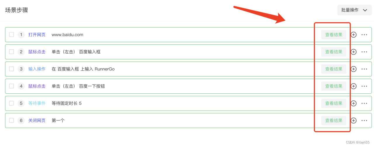
Runner GoUI自动化测试发布
构建自动化测试体系是当下每个项目团队愿意去做的,自动化测试减少重复操作节省人力成本。 RunnerGo UI自动化平台 RunnerGo提供从API管理到API性能再到可视化的API自动化、UI自动化测试功能模块,覆盖了整个产品测试周期。 RunnerGo UI自动化基于Selen…...

【Gensim概念】03/3 NLP玩转 word2vec
第三部分 对象函数 八 word2vec对象函数 该对象本质上包含单词和嵌入之间的映射。训练后,可以直接使用它以各种方式查询这些嵌入。有关示例,请参阅模块级别文档字符串。 类型 KeyedVectors 1) add_lifecycle_event(event_name, log_level2…...
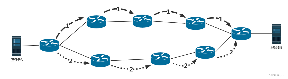
【网络协议】聊聊网络路由相关算法
如何配置路由 路由器是一台网络设备,多张网卡,当一个入口的网络包到达路由器时,会根据本地的信息库决定如何正确的转发流量,通常称为路由表 路由表主要包含如下 核心思想是根据目的 IP 地址来配置路由 目的网络:要去…...
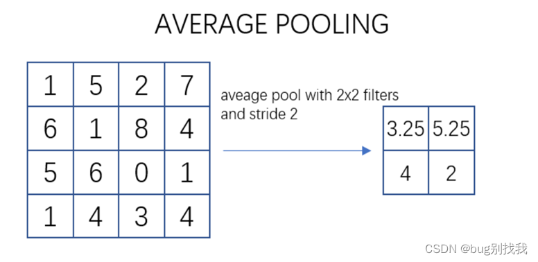
Python 深度学习入门之CNN
CNN 前言一、CNN简介1、简介2、结构 二、CNN简介1、输出层2、卷积层3、池化层4、全连接层5、输出层 前言 1024快乐!1024快乐!今天开新坑,学点深度学习相关的,说下比较火的CNN。 一、CNN简介 1、简介 CNN的全称是Convolutiona…...

国产开发板上打造开源ThingsBoard工业网关--基于米尔芯驰MYD-JD9X开发板
本篇测评由面包板论坛的优秀测评者“JerryZhen”提供。 本文将介绍基于米尔电子MYD-JD9X开发板打造成开源的Thingsboard网关。 Thingsboard网关是一个开源的软件网关,采用python作为开发语言,可以部署在任何支持 python 运行环境的主机上,灵…...

英语——语法——从句——名词性从句——笔记
文章目录 名词性从句一、定义二、分类(一)宾语从句(二)主语从句(三)C同位语从句(四)D表语从句 名词性从句 一、句子成分 简而言之,构成一个句子的成分(或要素…...

Nine PRO 邮箱 APP专业高级版 邮箱合集整理 一个就够了
软件简介: Nine 是一款面向 Android 的专业级电子邮件客户端,主打 Exchange 生态深度适配、本地数据存储与全链路安全,集邮件、日历、联系人、任务与笔记于一体,是商务办公与多账户管理的高效工具。 核心定位: 专为 …...

Go语言的Kubernetes编排实践
Go语言的Kubernetes编排实践 1. Kubernetes简介 Kubernetes(简称K8s)是一个开源的容器编排平台,用于自动化容器的部署、扩展和管理。它提供了强大的容器编排能力,使应用程序能够在分布式环境中高效运行。 1.1 Kubernetes的核心概念…...

Go语言的Docker容器化部署
Go语言的Docker容器化部署 1. Docker简介 Docker是一种容器化技术,它允许将应用程序及其依赖项打包到一个轻量级、可移植的容器中,然后在任何支持Docker的环境中运行。Docker的出现大大简化了应用的部署和管理过程,特别是在微服务架构中。 Do…...
_kaic)
weixin283基于微信小程序校园订餐的设计与开发+ssm(文档+源码)_kaic
第5章 系统实现 5.1用户登录功能的界面实现 本系统中可以保证安全的功能就是用户登录功能,登录可以验证用户的身份,用户可以注册,当密码忘记后也可以通过忘记密码功能进行找回。在用户登录界面里采用上中下的方式进行设计。在上设计的是功能…...

WarcraftHelper:魔兽争霸III体验增强与兼容性优化工具
WarcraftHelper:魔兽争霸III体验增强与兼容性优化工具 【免费下载链接】WarcraftHelper Warcraft III Helper , support 1.20e, 1.24e, 1.26a, 1.27a, 1.27b 项目地址: https://gitcode.com/gh_mirrors/wa/WarcraftHelper WarcraftHelper是一款专注于解决魔兽…...

量子纠缠与量子网络技术解析
3个关于诺贝尔物理学奖的问题与Antia Lamas-Linares的对话 某机构量子通信项目负责人谈及诺贝尔奖得主对她所在领域的影响。 作者:Larry Hardesty 2022年10月12日 5分钟阅读 上周,瑞典皇家科学院宣布,约翰克劳泽、阿兰阿斯佩和安东蔡林格因“…...

NFL十年追踪数据与机器学习创新
某机构十年NFL下一代数据统计创新 每场NFL比赛都会产生数百万个来自22名佩戴RFID设备的球员的追踪数据点。75个机器学习模型在云端处理这些数据,耗时不到一秒,将橄榄球运动转变为每一次移动都被测量、建模并即时分析的运动。 最初,每支俱乐部…...

Rufus技术转型中的兼容性管理:从Windows 7支持终止看开源项目的演进策略
Rufus技术转型中的兼容性管理:从Windows 7支持终止看开源项目的演进策略 【免费下载链接】rufus The Reliable USB Formatting Utility 项目地址: https://gitcode.com/GitHub_Trending/ru/rufus 技术变革背景:软件生命周期与系统迭代的必然冲突 …...

2025最权威的六大降AI率神器横评
Ai论文网站排名(开题报告、文献综述、降aigc率、降重综合对比) TOP1. 千笔AI TOP2. aipasspaper TOP3. 清北论文 TOP4. 豆包 TOP5. kimi TOP6. deepseek 对维普系统而言,在检测AI生成内容之际,它能够凭借多种办法来降低相似…...

专业级AI教材写作方法,低查重保障,让教材编写更高效
编写教材难题与 AI 工具解决方案 编写教材时,如何有效地满足多样化的需求?不同年级的学生在认知水平上存在着显著差异,内容如果过于复杂或简单都难以奏效;课堂教学和自主学习等不同场景的需求又各不相同,教材的呈现方…...